Modular Synth
Welcome to the documentation for Modular Synth, a node-based modular audio synthesizer built in Rust.
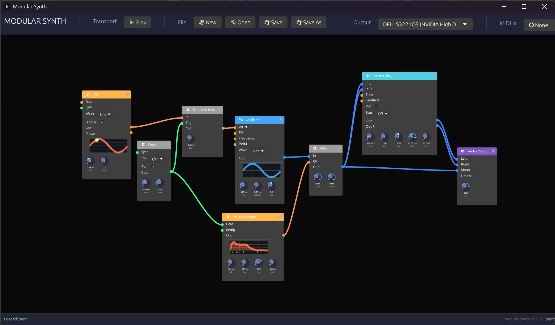 The Modular Synth interface showing a basic patch
What is Modular Synth?
Modular Synth takes a different approach from traditional virtual modular synthesizers. Instead of emulating physical hardware with skeuomorphic interfaces, it uses a clean node-graph approach similar to Blender's node editor or Unreal Engine's Blueprints.
This design philosophy offers several advantages:
- Clarity: Signal flow is immediately visible through color-coded connections
- Flexibility: Modules can be freely arranged without physical constraints
- Efficiency: Clean UI focuses on the essentials without decorative elements
- Learning: The visual representation helps understand synthesis concepts
Design Philosophy
Visual Feedback Over Skeuomorphism
While hardware emulations try to recreate the look of physical synthesizers, Modular Synth prioritizes information density and visual feedback. Every element serves a purpose:
- Color-coded signals tell you instantly what type of data flows through each connection
- Animated knobs show real-time modulation when controlled externally
- Waveform displays provide immediate visual confirmation of signal content
Node Graph Architecture
The node-graph paradigm brings several benefits:
- Scalable patches: Zoom out to see the big picture, zoom in for details
- Flexible layout: Arrange modules to match your mental model of the patch
- Clear connections: Bezier curves with signal-type coloring make routing obvious
- No cable spaghetti: Connections can cross without confusion thanks to color coding
Signal Types
Modular Synth uses four distinct signal types, each with its own color:
| Signal | Color | Purpose |
|---|---|---|
| Audio | Blue | Sound signals (-1.0 to 1.0) |
| Control | Orange | Modulation and CV (0.0 to 1.0 or bipolar) |
| Gate | Green | Triggers and gates (on/off) |
| MIDI | Purple | Note and controller data |
Learn more in Signal Types.
Module Categories
Modules are organized into functional categories, each with a distinctive header color:
- Sources (Blue) - Sound generators like oscillators
- Filters (Green) - Frequency shaping modules
- Modulation (Orange) - Envelopes, LFOs, and clocks
- Utilities (Yellow) - VCAs, mixers, and signal processors
- Effects (Purple) - Delays, reverbs, and other effects
- MIDI (Magenta) - MIDI input and processing
- Output (Red) - Final audio output
Getting Started
Ready to dive in? Here's the recommended path:
- Installation - Get Modular Synth running on your system
- Interface Overview - Learn the UI basics
- Your First Patch - Build a simple synthesizer
Or jump straight to the Module Reference if you're already familiar with modular synthesis.
Technical Foundation
Modular Synth is built with:
- Rust - For performance and safety
- egui - Immediate-mode GUI framework
- cpal - Cross-platform audio I/O
- Lock-free architecture - UI and audio threads communicate without blocking
The audio engine uses pre-allocated buffers and lock-free ring buffers to ensure glitch-free audio processing.
Installation
Modular Synth is built from source using Rust's Cargo build system.
Prerequisites
Rust Toolchain
Install the Rust toolchain via rustup:
# On Windows (PowerShell)
winget install Rustlang.Rustup

# On macOS/Linux
curl --proto '=https' --tlsv1.2 -sSf https://sh.rustup.rs | sh
Verify the installation:
rustc --version
cargo --version
Platform-Specific Dependencies
Windows
No additional dependencies required. The WASAPI audio backend is included with Windows.
macOS
No additional dependencies required. CoreAudio is included with macOS.
Linux
Install the ALSA development libraries:
# Debian/Ubuntu
sudo apt install libasound2-dev

# Fedora
sudo dnf install alsa-lib-devel

# Arch Linux
sudo pacman -S alsa-lib
Building from Source
Clone the Repository
git clone https://github.com/your-repo/modular.git
cd modular
Build and Run
For development (faster compilation, slower runtime):
cargo run
For release (slower compilation, optimized runtime):
cargo run --release
The release build is recommended for actual music-making, as it provides significantly better audio performance with lower CPU usage.
Build Options
Debug Build
cargo build
Creates an unoptimized binary in target/debug/ with debug symbols for development and troubleshooting.
Release Build
cargo build --release
Creates an optimized binary in target/release/ suitable for regular use.
Running Tests
cargo test
Troubleshooting
Audio Device Not Found
If you receive an audio device error:
- Check that your audio device is connected and working
- Verify no other application has exclusive access to the audio device
- Try a different sample rate if available
High CPU Usage
If you experience high CPU usage or audio glitches:
- Use the release build (
cargo run --release) - Reduce the number of active modules
- Check that your audio buffer size is appropriate (larger buffers reduce CPU but increase latency)
Linux: ALSA Underruns
If you experience audio dropouts on Linux:
- Ensure the ALSA development libraries are installed
- Try increasing the audio buffer size
- Consider running with real-time priority (requires appropriate permissions)
Next Steps
Once you have Modular Synth running:
- Interface Overview - Learn to navigate the UI
- Your First Patch - Build your first synthesizer
Interface Overview
Modular Synth uses a node-graph interface where modules are represented as nodes that can be connected together to create synthesizer patches.
 The main Modular Synth interface
The Canvas
The main area of the interface is the node graph canvas. This is where you create and connect modules.
Navigation
| Action | Mouse | Keyboard |
|---|---|---|
| Pan | Middle-click drag | Arrow keys |
| Zoom | Scroll wheel | + / - |
| Fit to view | - | Home |
| Select module | Left-click | - |
| Multi-select | Shift + left-click | - |
| Box select | Left-click drag on empty space | - |
| Delete | - | Delete or Backspace |
Canvas Tips
- Double-click empty space to quickly add a module
- Use the scroll wheel to zoom in for detailed work or out for an overview
- Modules can be freely positioned anywhere on the canvas
Adding Modules
Context Menu
Right-click on empty canvas space to open the module browser:
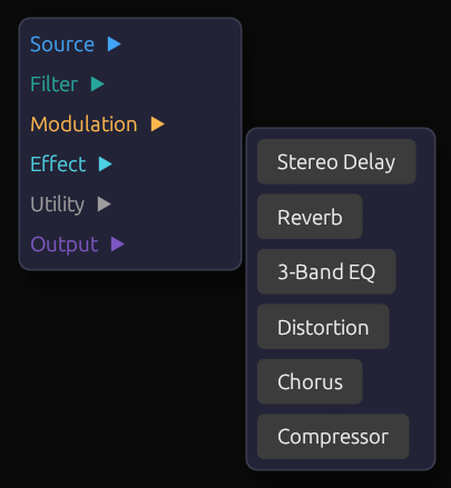 The module browser context menu
Modules are organized by category:
- Sources - Oscillators and sound generators
- Filters - Frequency shaping
- Modulation - Envelopes, LFOs, clocks
- Utilities - VCAs, mixers, signal processing
- Effects - Delays, reverbs, distortion
- MIDI - MIDI input and processing
- Visualization - Scopes and meters
- Output - Audio output
Click a module name to add it at the cursor position.
Quick Add
Double-click on empty canvas space to open a quick search box where you can type to filter modules by name.
Module Anatomy
Each module has a consistent structure:
 Parts of a module
Header Bar
The colored bar at the top shows:
- Module name - The type of module
- Category color - Indicates the module's function category
Input Ports (Left Side)
Circular connectors on the left side receive signals from other modules:
- Port color indicates the expected signal type
- Port label describes what the input controls
- Hover over a port to see a tooltip with details
Output Ports (Right Side)
Circular connectors on the right side send signals to other modules:
- Port color indicates the signal type produced
- Multiple modules can connect to the same output
Parameter Knobs (Bottom)
Rotary knobs for adjusting module parameters:
- Drag vertically to adjust the value
- Double-click to reset to default
- Ctrl + click for fine adjustment
- Value readout shows the current setting
Exposed Parameters
Some parameters can be controlled both manually and via external signals. When an external signal is connected:
- The knob becomes read-only (dimmed appearance)
- The knob animates to show the incoming signal value
- An orange indicator shows external control is active
When disconnected, the knob returns to manual control.
Making Connections
Creating a Connection
- Click and hold on an output port (right side of a module)
- Drag to an input port (left side of another module)
- Release to complete the connection
 Dragging a connection from output to input
Connection Rules
- Outputs connect to inputs (never output-to-output or input-to-input)
- Signal types should match (Audio to Audio, Control to Control, etc.)
- Some inputs accept multiple signal types (automatic conversion)
- Multiple cables can connect to the same output
- Only one cable can connect to each input
Connection Colors
Cables are colored by signal type:
| Color | Signal Type |
|---|---|
| Blue | Audio |
| Orange | Control/CV |
| Green | Gate/Trigger |
| Purple | MIDI |
Removing Connections
- Right-click on a connection to delete it
- Click on an input port with an existing connection, then press
Escapeto disconnect - Delete a module to remove all its connections
Adjusting Parameters
Knob Interaction
 Adjusting a parameter knob
| Action | Result |
|---|---|
| Drag up/down | Adjust value |
| Ctrl + drag | Fine adjustment |
| Double-click | Reset to default |
| Right-click | Open value entry / MIDI learn |
Value Display
Below each knob is a value readout showing:
- The current numeric value
- The unit (Hz, ms, dB, etc.) where applicable
Patch Management
Saving Patches
| Action | Shortcut |
|---|---|
| Save | Ctrl + S |
| Save As | Ctrl + Shift + S |
Patches are saved as .json files containing all module settings and connections.
Loading Patches
| Action | Shortcut |
|---|---|
| Open | Ctrl + O |
| New | Ctrl + N |
Recent Patches
Access recently opened patches from the File menu.
MIDI Setup
Enabling MIDI Input
- Add a MIDI Note or Keyboard module to your patch
- The module will automatically receive input from connected MIDI devices
MIDI Learn
To assign a MIDI controller to a knob:
- Right-click the knob
- Select MIDI Learn
- Move the desired MIDI controller
- The knob is now mapped to that controller
Computer Keyboard
The Keyboard module allows playing notes using your computer keyboard:
- Z-M row: Lower octave (C3-B3)
- Q-P row: Upper octave (C4-B4)
- Number keys: Octave selection
Keyboard Shortcuts
General
| Shortcut | Action |
|---|---|
Ctrl + N | New patch |
Ctrl + O | Open patch |
Ctrl + S | Save patch |
Ctrl + Shift + S | Save patch as |
Ctrl + Z | Undo |
Ctrl + Y | Redo |
Delete | Delete selected |
Ctrl + A | Select all |
Escape | Deselect / Cancel |
Navigation
| Shortcut | Action |
|---|---|
Home | Fit all to view |
+ / - | Zoom in / out |
| Arrow keys | Pan canvas |
Modules
| Shortcut | Action |
|---|---|
Ctrl + D | Duplicate selected |
Ctrl + C | Copy selected |
Ctrl + V | Paste |
Next Steps
Now that you understand the interface:
- Your First Patch - Build a simple synthesizer step by step
- Signal Types - Understand the different signal types
- Module Reference - Explore all available modules
Your First Patch
Let's build a simple synthesizer patch from scratch. By the end of this tutorial, you'll have a playable synthesizer with an oscillator, filter, envelope, and output.
 The completed first patch
Step 1: Add an Oscillator
Every synthesizer needs a sound source. Let's start with an oscillator.
- Right-click on the canvas to open the module browser
- Navigate to Sources > Oscillator
- Click to add the oscillator
 Adding an oscillator from the context menu
The oscillator generates a continuous tone. By default, it produces a sine wave at 440 Hz (the note A4).
Oscillator Settings
- Waveform: Select between Sine, Saw, Square, or Triangle
- Frequency: The pitch in Hz (or controlled by V/Oct input)
- Detune: Fine-tune adjustment in cents
Try changing the waveform to Saw for a brighter, more harmonically rich sound.
Step 2: Add Audio Output
To hear the oscillator, we need to connect it to the audio output.
- Right-click on the canvas
- Navigate to Output > Audio Output
- Click to add the output module
Position it to the right of the oscillator.
Connect the Oscillator to Output
- Click on the oscillator's Audio Out port (right side, blue)
- Drag to the output's Left input port
- Release to create the connection
 Connecting the oscillator to the output
You should now hear a continuous tone! If not, check that:
- Your audio device is working
- The output module's Level knob is turned up
- Your system volume is audible
Stereo Output
For stereo sound, also connect the oscillator to the Right input, or use the Mono input which sends to both channels.
Step 3: Control the Pitch
A synthesizer that plays only one note isn't very useful. Let's add keyboard control.
- Right-click > MIDI > Keyboard Input
- Position it to the left of the oscillator
Connect Keyboard to Oscillator
- Connect the keyboard's V/Oct output to the oscillator's V/Oct input
- Connect the keyboard's Gate output (we'll use this later)
 Keyboard controlling the oscillator pitch
Now press keys on your computer keyboard:
- Z, X, C, V, B, N, M play notes C through B
- A, S, D, F, G, H, J play sharps/flats
- Q-P row plays an octave higher
The oscillator pitch follows your keyboard input!
Step 4: Add an Envelope
Right now, the sound plays continuously. An envelope shapes the sound over time, giving it a beginning and end.
- Right-click > Modulation > ADSR Envelope
- Position it between the keyboard and output
Envelope Parameters
The ADSR envelope has four stages:
- Attack: How quickly the sound rises (0 = instant, higher = gradual fade in)
- Decay: How quickly it falls to the sustain level
- Sustain: The level held while the key is pressed
- Release: How quickly the sound fades after key release
Set these initial values:
- Attack: 10ms (quick start)
- Decay: 200ms (moderate decay)
- Sustain: 0.5 (half volume while held)
- Release: 300ms (gentle fade out)
Connect the Envelope
- Connect the keyboard's Gate output to the envelope's Gate input
- Connect the envelope's Env output to... we need a VCA!
Step 5: Add a VCA
A VCA (Voltage Controlled Amplifier) controls the volume of a signal. We'll use it to apply the envelope to our oscillator.
- Right-click > Utilities > VCA
- Position it between the oscillator and output
Connect Everything
- Disconnect the oscillator from the output (right-click the cable)
- Connect the oscillator's Audio Out to the VCA's Input
- Connect the envelope's Env output to the VCA's CV input
- Connect the VCA's Output to the audio output's Mono input
 The patch with VCA and envelope
Now when you press a key:
- The keyboard sends Gate and V/Oct
- The envelope responds to the Gate
- The VCA shapes the oscillator volume based on the envelope
Try adjusting the envelope parameters to change the character of the sound!
Step 6: Add a Filter
Filters shape the harmonic content of a sound by removing frequencies. Let's add a low-pass filter to warm up our tone.
- Right-click > Filters > SVF Filter
- Position it between the oscillator and VCA
Connect the Filter
- Disconnect the oscillator from the VCA
- Connect oscillator Audio Out to filter Input
- Connect filter Lowpass output to VCA Input
Filter Settings
- Cutoff: The frequency where filtering begins (lower = darker sound)
- Resonance: Emphasizes frequencies at the cutoff (creates a peak)
Set cutoff to around 1000 Hz and resonance to 0.3 for a warm, slightly vocal quality.
 Adding the SVF filter to the signal chain
Step 7: Modulate the Filter (Optional)
For a more dynamic sound, let's make the filter open and close with each note using the envelope.
Add Filter Envelope Control
You can use the same envelope or add a second one:
- Connect the envelope's Env output to the filter's Cutoff input
Now the filter cutoff follows the envelope shape:
- Filter opens during attack
- Closes during decay
- Stays partially open during sustain
- Closes during release
Adjust the Cutoff knob to set the baseline, and the envelope adds movement on top.
Complete Patch Overview
Here's the final signal flow:
[Keyboard] ──V/Oct──> [Oscillator] ──Audio──> [Filter] ──Audio──> [VCA] ──Audio──> [Output]
    │                                            ↑                   ↑
    └───────Gate────> [ADSR Envelope] ───────────┴───────────────────┘
 The complete first patch
What You've Learned
- Adding modules from the context menu
- Connecting modules by dragging between ports
- Signal flow: Oscillator → Filter → VCA → Output
- Control signals: Gate triggers the envelope, V/Oct controls pitch
- Modulation: Using the envelope to control both VCA and filter
Experimentation Ideas
Try these modifications:
- Change the waveform - Saw and Square have more harmonics for the filter to work with
- Add an LFO - Connect it to the filter cutoff for a wobbling effect
- Increase resonance - Higher resonance creates a more dramatic filter sweep
- Adjust envelope - Long attack creates pad sounds, short attack creates plucks
- Add reverb - Insert a reverb effect between VCA and output
Next Steps
Now that you've built your first patch:
- Signal Types - Understand the different signal types in depth
- Module Reference - Explore all available modules
- Basic Subtractive Synth - A more complete subtractive synthesizer recipe
- FM Synthesis - Try a different synthesis technique
Signal Types
Modular Synth uses a type system for signals that helps you understand what kind of data flows through each connection. Each signal type has a distinctive color, making it easy to trace the flow of audio, control, gate, and MIDI signals through your patch.
Overview
| Type | Color | Range | Primary Use |
|---|---|---|---|
| Audio | Blue | -1.0 to 1.0 | Sound signals |
| Control | Orange | 0.0 to 1.0 (unipolar) or -1.0 to 1.0 (bipolar) | Modulation, CV |
| Gate | Green | 0.0 or 1.0 | Triggers, on/off states |
| MIDI | Purple | Structured data | Note/CC messages |
 The four signal types with their colors
Audio Signals
Color: Blue
Audio signals carry the actual sound you hear. They oscillate rapidly (typically 20 Hz to 20 kHz) and represent the waveform that will be sent to your speakers.
Characteristics
- Range: -1.0 to 1.0 (bipolar)
- Sample Rate: Matches your audio interface (typically 44.1 kHz or 48 kHz)
- Bandwidth: Full audio spectrum
Common Sources
- Oscillators (all waveforms)
- Filter outputs
- Effect outputs
- Sample playback
Common Destinations
- Filter inputs
- Effect inputs
- VCA inputs
- Audio Output module
Signal Level
Audio signals should stay within the -1.0 to 1.0 range to avoid clipping (distortion). The Audio Output module includes a limiter to prevent harsh digital clipping, but it's best to manage levels throughout your patch.
Control Signals
Color: Orange
Control signals (also called CV or Control Voltage) carry slower-moving data used to modulate parameters. They don't produce sound directly but shape and control other modules.
Characteristics
- Unipolar Range: 0.0 to 1.0 (e.g., envelope output, LFO with offset)
- Bipolar Range: -1.0 to 1.0 (e.g., bipolar LFO)
- Bandwidth: Typically low frequency (< 100 Hz), but can be audio rate
Common Sources
- Envelopes (ADSR)
- LFOs
- Sequencers
- MIDI CC (converted to CV)
- Attenuverters
Common Destinations
- Filter cutoff
- Oscillator frequency (FM)
- VCA CV input
- Effect parameters
- Any "modulatable" parameter
Unipolar vs. Bipolar
Unipolar (0.0 to 1.0):
- Always positive
- Good for controlling parameters that shouldn't go negative
- Examples: envelope output, volume control
Bipolar (-1.0 to 1.0):
- Swings positive and negative
- Good for vibrato, filter sweeps that go both ways
- Examples: LFO output, pitch modulation
V/Oct (Volts per Octave)
A special control signal convention where each 1.0 increase represents one octave up in pitch. This allows precise musical pitch control:
- 0.0 = Base frequency (e.g., C0)
- 1.0 = One octave up (C1)
- 2.0 = Two octaves up (C2)
- 0.5 = Half octave up (F#0)
- -1.0 = One octave down (C-1)
The Keyboard and MIDI Note modules output V/Oct signals for controlling oscillator pitch.
Gate Signals
Color: Green
Gate signals are binary on/off signals used for triggering events. Unlike audio or control signals that vary continuously, gates are either fully on (1.0) or fully off (0.0).
Characteristics
- Range: 0.0 (off) or 1.0 (on)
- Transitions: Rising edge (0→1) and falling edge (1→0)
- Duration: The time the gate stays high
Gate vs. Trigger
While both use the green color, there's a conceptual difference:
Gate: Stays high for a duration (like holding a key)
- Used for: Envelope gate input, held notes
Trigger: Brief pulse (like a drum hit)
- Used for: Clock pulses, one-shot events
Most modules respond appropriately to both.
Common Sources
- Keyboard/MIDI Note (key pressed/released)
- Clock modules (rhythmic pulses)
- Sequencers (step triggers)
- LFOs in square wave mode
Common Destinations
- Envelope gate input
- Sample & Hold trigger
- Sequencer clock input
- Any module that responds to triggers
Edge Detection
Some modules respond to:
- Rising edge: The moment gate goes from 0 to 1
- Falling edge: The moment gate goes from 1 to 0
- Gate high: While the gate is 1
- Gate low: While the gate is 0
For example, an ADSR envelope:
- Begins Attack on rising edge
- Enters Release on falling edge
MIDI Signals
Color: Purple
MIDI signals carry structured musical data including note events, control changes, and other MIDI messages. Unlike the other signal types which are continuous values, MIDI signals contain discrete events.
Characteristics
- Format: Structured messages (Note On/Off, CC, etc.)
- Data: Note number, velocity, channel, CC values
- Timing: Event-based rather than continuous
Common Sources
- MIDI Note module (from external MIDI devices)
- Keyboard module (from computer keyboard)
Common Destinations
- MIDI Monitor (for debugging)
- Modules that accept MIDI input directly
MIDI to CV Conversion
Most modules don't work with MIDI directly. The MIDI Note module converts MIDI to:
- V/Oct: Note number → pitch CV
- Gate: Note On/Off → gate signal
- Velocity: Note velocity → control signal
This conversion allows standard synthesis modules to respond to MIDI input.
Signal Type Compatibility
Automatic Conversion
Some connections perform automatic conversion:
| From | To | Conversion |
|---|---|---|
| Audio | Control | Treated as control signal |
| Control | Audio | Treated as audio (modulation) |
| Gate | Control | 0.0 or 1.0 control value |
| Control | Gate | Threshold at 0.5 |
Best Practices
While some conversions work, it's best to match signal types:
- Audio to audio: Full bandwidth sound processing
- Control to control: Modulation and CV routing
- Gate to gate: Trigger and timing signals
- MIDI to MIDI modules: Then convert to CV
Audio-Rate Modulation
Control signals can run at audio rate for special effects:
- FM Synthesis: Audio-rate modulation of oscillator frequency
- Ring Modulation: Audio-rate amplitude modulation
- Filter FM: Audio-rate cutoff modulation for unusual timbres
Visual Identification
Port Colors
Input and output ports are colored to indicate the expected signal type:
 Ports showing their signal type colors
Cable Colors
Cables inherit the color of the signal they carry, making it easy to trace signal flow:
 Cables colored by signal type
Module Headers
Module header colors indicate the category, not signal type:
- Blue header = Source (produces audio signals)
- Green header = Filter (processes audio signals)
- Orange header = Modulation (produces control signals)
- etc.
Next Steps
- Connections - Learn the rules for connecting modules
- Module Reference - See signal types for each module
Connections
Connections are the cables that link modules together, allowing signals to flow through your patch. Understanding connection rules helps you build effective synthesizer patches.
Basic Rules
Outputs to Inputs
Connections always flow from output ports (right side of modules) to input ports (left side of modules).
 Signals flow from outputs (right) to inputs (left)
You cannot:
- Connect output to output
- Connect input to input
- Create circular connections that would cause feedback loops (the system prevents this)
One Input, Many Outputs
Inputs accept only one connection at a time. Connecting a new cable to an already-connected input will replace the existing connection.
Outputs can feed multiple inputs. The signal is copied to each destination without reduction in level.
 One output feeding multiple inputs
Making Connections
Creating a Connection
- Click and hold on an output port
- Drag toward the destination input
- The cursor will show valid connection points
- Release over an input port to complete
 Dragging to create a connection
Visual Feedback
While dragging:
- Valid inputs highlight to show they can accept the connection
- Invalid inputs (wrong signal type or already connected) may dim
- The cable preview shows the signal type color
Quick Connect
Double-click an output port to start a connection, then single-click an input to complete it. This is useful for long-distance connections.
Removing Connections
Right-Click Method
Right-click on a cable to delete it immediately.
Disconnect from Port
Click on a connected input port, then press Escape to disconnect.
Delete Module
Deleting a module automatically removes all its connections.
Signal Type Matching
Preferred Connections
For best results, match signal types:
| Connection | Result |
|---|---|
| Audio → Audio | Full-bandwidth sound signal |
| Control → Control | Modulation and CV |
| Gate → Gate | Trigger and timing |
| MIDI → MIDI | MIDI message passing |
Cross-Type Connections
Some cross-type connections are useful:
| Connection | Use Case |
|---|---|
| Audio → Control | Audio-rate modulation (FM synthesis) |
| Gate → Control | Simple 0/1 control signal |
| Control → Audio | Slow modulation mixed as audio |
The system allows most cross-type connections, treating the signal according to the destination's expectations.
MIDI Special Case
MIDI signals are structured differently and generally only connect to MIDI-specific inputs. Use the MIDI Note module to convert MIDI to CV signals (V/Oct, Gate, Velocity) for standard modules.
Cable Colors
Cables are colored by signal type for easy visual identification:
| Color | Signal Type |
|---|---|
| Blue | Audio |
| Orange | Control/CV |
| Green | Gate/Trigger |
| Purple | MIDI |
 Cables colored by signal type
This coloring helps you:
- Trace signal flow through complex patches
- Identify signal types at a glance
- Debug routing issues
Connection Tips
Keep It Organized
- Position modules so signal flows left-to-right
- Group related modules together
- Use the canvas space to prevent cable crossings
 A well-organized patch with clear signal flow
Modulation Routing
Control signals often "reach across" the main signal flow:
[LFO] ────────────────────────┐
                              ↓ (CV)
[Osc] ──> [Filter] ──> [VCA] ──> [Out]
            ↑
[Envelope] ─┘
Position modulation sources (LFOs, envelopes) above or below the main signal path.
Check Signal Flow
If you're not getting sound:
- Trace from output backward - Is the Audio Output connected?
- Check control signals - Is the VCA getting a CV signal?
- Verify gates - Is the envelope receiving a gate?
- Look at signal types - Are the right types connected?
Exposed Parameters
Some module parameters can be controlled via connections. These are called "exposed" parameters.
How It Works
When a parameter is exposed:
- It has both a knob for manual control AND an input port for external control
- When disconnected: The knob controls the parameter normally
- When connected: The external signal takes over
Visual Indicators
 An exposed parameter showing external control
When externally controlled:
- The knob becomes read-only (dimmed)
- The knob animates to show the incoming signal value
- An orange indicator dot shows external control is active
Combining Manual and Modulation
The external signal often adds to the knob's base value:
- Knob sets the center/base value
- Input adds modulation on top
For example, a filter cutoff:
- Knob at 1000 Hz
- LFO input swinging ±500 Hz
- Result: Cutoff sweeps between 500-1500 Hz
Advanced Topics
Audio-Rate Modulation
Control inputs can accept audio-rate signals for special effects:
- FM Synthesis: Oscillator frequency modulated at audio rate
- AM/Ring Mod: Amplitude modulated at audio rate
- Filter FM: Cutoff modulated at audio rate
Feedback Loops
The system prevents direct feedback loops (output connecting back to earlier input in the same signal path). This is necessary to maintain stable, real-time audio processing.
For delay-based feedback effects, use the Delay module's built-in feedback control.
DC Offset
Control signals may have DC offset (a constant value added to the signal). Some modules include DC blocking or offset controls to manage this.
Troubleshooting
No Sound
- Check that Audio Output is connected
- Verify VCA is receiving CV or is set to pass audio
- Ensure oscillator is running (not waiting for trigger)
- Check system audio settings
Unexpected Sound
- Look for unintended connections
- Check signal levels (may need attenuation)
- Verify signal types match expectations
Clicking or Popping
- Ensure control signals are smoothed
- Check for abrupt gate transitions
- Add slight attack/release to envelopes
Next Steps
- Module Reference - See connection details for each module
- Your First Patch - Practice making connections
Module Overview
Modular Synth includes 22 modules organized into functional categories. Each category has a distinctive header color for quick identification.
Categories
Sources (Blue Header)
Sound generators that create audio signals from scratch.
| Module | ID | Description |
|---|---|---|
| Oscillator | osc.sine | Multi-waveform VCO with FM and PWM |
Filters (Green Header)
Frequency-shaping modules that remove or emphasize parts of the spectrum.
| Module | ID | Description |
|---|---|---|
| SVF Filter | filter.svf | State Variable Filter with LP/HP/BP outputs |
Modulation (Orange Header)
Modules that generate control signals for modulating other parameters.
| Module | ID | Description |
|---|---|---|
| ADSR Envelope | mod.adsr | Attack/Decay/Sustain/Release envelope generator |
| LFO | mod.lfo | Low Frequency Oscillator with multiple waveforms |
| Clock | mod.clock | Clock generator with BPM control and divisions |
Utilities (Yellow Header)
Signal processing and routing modules.
| Module | ID | Description |
|---|---|---|
| VCA | util.vca | Voltage Controlled Amplifier |
| Mixer | util.mixer | 2-channel audio/CV mixer |
| Attenuverter | util.attenuverter | Scale, invert, and offset signals |
| Sample & Hold | util.samplehold | Sample input on trigger |
| Sequencer | util.sequencer | 16-step CV/gate sequencer |
Effects (Purple Header)
Audio processing effects.
| Module | ID | Description |
|---|---|---|
| Delay | fx.delay | Stereo delay with feedback and filtering |
| Reverb | fx.reverb | Algorithmic reverb |
| Chorus | fx.chorus | Chorus/ensemble effect |
| Distortion | fx.distortion | Waveshaping distortion |
| EQ | fx.eq | 3-band parametric equalizer |
| Compressor | fx.compressor | Dynamics compressor |
MIDI (Magenta Header)
MIDI input and processing modules.
| Module | ID | Description |
|---|---|---|
| Keyboard Input | midi.keyboard | Computer keyboard to CV/Gate |
| MIDI Note | midi.note | MIDI to V/Oct, Gate, and Velocity |
| MIDI Monitor | midi.monitor | Display incoming MIDI data |
Visualization (Cyan Header)
Visual feedback modules.
| Module | ID | Description |
|---|---|---|
| Oscilloscope | util.oscilloscope | Waveform display |
Output (Red Header)
Final audio output.
| Module | ID | Description |
|---|---|---|
| Audio Output | output.audio | Stereo output with limiter |
Signal Type Quick Reference
When connecting modules, match these signal types:
| Signal | Color | Typical Use |
|---|---|---|
| Audio | Blue | Sound signals between oscillators, filters, effects, output |
| Control | Orange | Modulation from envelopes, LFOs to parameters |
| Gate | Green | Triggers from keyboard, clock, sequencer to envelopes |
| MIDI | Purple | MIDI data to MIDI-processing modules |
Common Signal Chains
Basic Synthesis Path
[Oscillator] → [Filter] → [VCA] → [Output]
With Modulation
[Keyboard] ──V/Oct──→ [Oscillator] → [Filter] → [VCA] → [Output]
    │                                    ↑         ↑
    └──Gate──→ [Envelope] ──────────────┴─────────┘
With Effects
[Oscillator] → [Filter] → [VCA] → [Delay] → [Reverb] → [Output]
Sequenced Pattern
[Clock] → [Sequencer] ──CV──→ [Oscillator] → [Filter] → [Output]
              │                                  ↑
              └──Gate──→ [Envelope] ────────────┘
Choosing Modules
I want to...
Generate a sound: Start with Oscillator
Shape the tone: Use SVF Filter
Control volume: Use VCA with an Envelope
Add movement: Connect an LFO to a parameter
Play from keyboard: Add Keyboard Input or MIDI Note
Create rhythmic patterns: Use Clock and Sequencer
Add space/depth: Use Delay or Reverb
Mix multiple signals: Use Mixer
See what's happening: Add Oscilloscope
Hear the result: Connect to Audio Output
Oscillator
Module ID: osc.sine
Category: Sources
Header Color: Blue
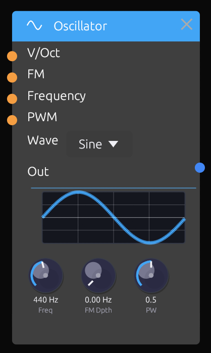 The Oscillator module
Description
The Oscillator is the primary sound source in Modular Synth. It generates periodic waveforms at audio frequencies, producing the raw tones that can be shaped by filters, envelopes, and effects.
This is a VCO (Voltage Controlled Oscillator), meaning its frequency can be controlled by external signals, enabling keyboard tracking and vibrato effects.
Inputs
| Port | Signal Type | Description |
|---|---|---|
| V/Oct | Control (Orange) | 1V/octave pitch control. Each 1.0 increase raises pitch by one octave |
| FM | Audio/Control (Blue/Orange) | Frequency modulation input. Modulates pitch at the rate of incoming signal |
| PWM | Control (Orange) | Pulse width modulation for square wave. Controls duty cycle |
| Sync | Gate (Green) | Hard sync input. Resets waveform phase on rising edge |
Outputs
| Port | Signal Type | Description |
|---|---|---|
| Audio Out | Audio (Blue) | Main audio output with selected waveform |
Parameters
| Knob | Range | Default | Description |
|---|---|---|---|
| Waveform | Sine/Saw/Square/Triangle | Sine | Selects the output waveform shape |
| Frequency | 20 Hz - 20 kHz | 440 Hz | Base frequency when no V/Oct is connected |
| Detune | -100 to +100 cents | 0 | Fine tune adjustment in cents (1/100th of a semitone) |
| FM Amount | 0.0 - 1.0 | 0.0 | Depth of frequency modulation from FM input |
| PW | 0.1 - 0.9 | 0.5 | Pulse width for square wave (0.5 = 50% duty cycle) |
Waveforms
Sine

Pure tone with no harmonics. Useful for:
- Sub-bass
- FM synthesis carriers
- Pure, flute-like tones
- Smooth modulation sources
Sawtooth (Saw)

Contains all harmonics with decreasing amplitude. Useful for:
- Classic synth leads and basses
- Strings and brass sounds
- Rich source material for filtering
Square

Contains odd harmonics only. Useful for:
- Hollow, woody tones
- Clarinet-like sounds
- PWM for chorus-like effects
Triangle

Contains odd harmonics with rapid rolloff. Useful for:
- Softer than square, brighter than sine
- Flute and soft lead sounds
- Smooth modulation
Usage Tips
Basic Pitch Control
Connect a keyboard or MIDI module's V/Oct output to control pitch:
[Keyboard] ──V/Oct──> [Oscillator]
The V/Oct standard means:
- 0.0 = Base frequency (set by Frequency knob)
- 1.0 = One octave up
- -1.0 = One octave down
- 0.083 = One semitone up (1/12 of an octave)
Vibrato with LFO
Connect an LFO to the FM input for vibrato:
[LFO] ──> [Oscillator FM]
- Use low FM Amount (0.1-0.2) for subtle vibrato
- Higher amounts create more dramatic pitch wobble
- LFO rate of 5-7 Hz is typical for vibrato
FM Synthesis
Connect another oscillator to FM input for FM synthesis:
[Oscillator 2] ──> [Oscillator 1 FM]
- Sine waves work best for clean FM tones
- Integer frequency ratios (2:1, 3:1) create harmonic sounds
- Non-integer ratios create inharmonic, bell-like tones
- FM Amount controls brightness/complexity
Pulse Width Modulation
For square wave, modulate pulse width with an LFO:
[LFO] ──> [Oscillator PWM]
- Creates a chorus-like, animated effect
- Extreme PW values (near 0.1 or 0.9) create thin, nasal tones
- Slow LFO rates create subtle movement
- Fast rates create more dramatic timbral changes
Hard Sync
Connect a sync signal to reset the waveform cycle:
[Oscillator 2 Out] ──> [Oscillator 1 Sync]
Hard sync creates complex, aggressive tones:
- Oscillator 1 (synced) resets when Oscillator 2 completes a cycle
- Sweep Oscillator 1's frequency for the classic sync sweep sound
- Works best when synced osc is higher frequency than master
Detuning for Thickness
Use two oscillators slightly detuned for a thicker sound:
[Osc 1 (Detune: 0)] ──┐
                      ├──> [Mixer] ──> [Filter]
[Osc 2 (Detune: +7)] ─┘
- Small detune values (5-15 cents) create subtle chorusing
- Larger values (20-50 cents) create a "supersaw" effect
Connection Examples
Typical Synthesis Chain
[Keyboard] ──V/Oct──> [Oscillator] ──> [Filter] ──> [VCA] ──> [Output]
FM Bell Patch
[Oscillator 1] ──FM──> [Oscillator 2] ──> [VCA] ──> [Output]
     (Modulator)           (Carrier)
Dual Oscillator with PWM
[LFO] ──> [Osc 1 PWM]
          [Osc 1] ──┐
                    ├──> [Mixer] ──> [Filter]
          [Osc 2] ──┘
Related Modules
- LFO - For vibrato and PWM modulation
- SVF Filter - Shape the oscillator's harmonics
- VCA - Control oscillator volume
- ADSR Envelope - Shape the sound over time
SVF Filter
Module ID: filter.svf
Category: Filters
Header Color: Green
 The SVF Filter module
Description
The State Variable Filter (SVF) is a versatile multi-mode filter that provides simultaneous lowpass, highpass, and bandpass outputs from a single input signal. This architecture allows you to blend different filter responses or switch between them without repatching.
The SVF design offers:
- Self-oscillation at high resonance (can be used as a sine oscillator)
- Smooth cutoff sweeps without artifacts
- Stable operation across all settings
- Simultaneous multi-mode outputs
Inputs
| Port | Signal Type | Description |
|---|---|---|
| Input | Audio (Blue) | Main audio input to be filtered |
| Cutoff | Control (Orange) | Modulation input for cutoff frequency |
| Resonance | Control (Orange) | Modulation input for resonance/Q |
Outputs
| Port | Signal Type | Description |
|---|---|---|
| Lowpass | Audio (Blue) | Lowpass output - passes frequencies below cutoff |
| Highpass | Audio (Blue) | Highpass output - passes frequencies above cutoff |
| Bandpass | Audio (Blue) | Bandpass output - passes frequencies around cutoff |
Parameters
| Knob | Range | Default | Description |
|---|---|---|---|
| Cutoff | 20 Hz - 20 kHz | 1000 Hz | Filter cutoff frequency |
| Resonance | 0.0 - 1.0 | 0.0 | Resonance/Q - emphasis at cutoff frequency |
| CV Amount | -1.0 - +1.0 | 0.0 | How much the Cutoff CV input affects the cutoff |
Filter Modes
Lowpass (LP)
 Lowpass frequency response
- Passes frequencies below the cutoff
- Removes high frequencies, creating a "darker" or "warmer" sound
- Most common filter type for synthesis
- At 12dB/octave slope (2-pole)
Use cases:
- Warming up bright oscillators
- Classic subtractive synthesis
- Bass sounds
- Removing harshness
Highpass (HP)
 Highpass frequency response
- Passes frequencies above the cutoff
- Removes low frequencies, creating a "thinner" or "brighter" sound
- At 12dB/octave slope (2-pole)
Use cases:
- Removing mud/rumble
- Creating thin, airy sounds
- Hi-hat and cymbal synthesis
- Clearing space in a mix
Bandpass (BP)
 Bandpass frequency response
- Passes frequencies around the cutoff
- Removes both low and high frequencies
- Width controlled by resonance
Use cases:
- Vocal/formant-like sounds
- Telephone/radio effect
- Isolating specific frequency ranges
- Wah-wah effects
Usage Tips
Basic Filtering
Connect an oscillator to soften its harmonics:
[Oscillator] ──> [Filter Input]
                 [Filter LP] ──> [VCA] ──> [Output]
- Start with cutoff around 1000 Hz
- Adjust cutoff to taste - lower = darker, higher = brighter
- Add slight resonance (0.2-0.4) for character
Filter Envelope
Create dynamic filter sweeps with an envelope:
[Keyboard] ──Gate──> [Envelope] ──> [Filter Cutoff CV]
- Set base cutoff low (200-500 Hz)
- Use positive CV Amount
- Short attack/decay creates "plucky" sounds
- Long attack creates "swelling" sounds
Filter + LFO (Wobble)
Create rhythmic filter movement:
[LFO] ──> [Filter Cutoff CV]
- Square LFO creates choppy, rhythmic effect
- Triangle/Sine LFO creates smooth wobble
- Adjust LFO rate and CV Amount for intensity
Self-Oscillation
At high resonance (near 1.0), the filter will self-oscillate, producing a sine wave at the cutoff frequency:
- Set resonance to ~0.95 or higher
- No input signal needed
- Control pitch via Cutoff CV
- Useful for pure sine tones and sound effects
Note: Self-oscillation can be loud - reduce output level first.
Tracking Keyboard
Make filter cutoff follow the keyboard:
[Keyboard] ──V/Oct──> [Oscillator V/Oct]
           ──V/Oct──> [Filter Cutoff CV]
This keeps the filter's relative brightness consistent across different pitches. Set CV Amount to achieve 1:1 tracking.
Parallel Filter Modes
Use multiple outputs simultaneously for complex sounds:
[Oscillator] ──> [Filter Input]
                 [Filter LP] ──> [Mixer Ch1]
                 [Filter BP] ──> [Mixer Ch2] ──> [Output]
Blend lowpass and bandpass for unique timbres.
Resonant Accents
High resonance emphasizes the cutoff frequency:
- Creates a "peak" or "ping" at the cutoff
- Useful for acid bass lines (TB-303 style)
- Combine with filter envelope for accent effects
Notch Filter (Advanced)
Combine highpass and lowpass outputs to create a notch:
[Filter LP] ──> [Mixer] (inverted) ──┐
[Filter HP] ──> [Mixer] ─────────────┴──> [Output]
The phase relationship creates a notch at the cutoff frequency.
Connection Examples
Classic Subtractive Synth
[Keyboard] ──V/Oct──> [Oscillator] ──> [Filter] ──> [VCA] ──> [Output]
           ──Gate───> [Envelope] ──────────┬─────────────┘
                                           └──> [Filter Cutoff CV]
Acid Bass
[Sequencer] ──CV──> [Oscillator (Saw)] ──> [Filter LP] ──> [Output]
            ──Gate──> [Envelope] ──> [Filter Cutoff CV]
                                     (Resonance: 0.7-0.9)
Wah Effect
[Guitar/Audio In] ──> [Filter BP] ──> [Output]
                      [Expression Pedal] ──> [Filter Cutoff CV]
Sound Design Tips
| Sound | Cutoff | Resonance | Modulation |
|---|---|---|---|
| Warm pad | 800 Hz | 0.1 | Slow LFO |
| Acid bass | 300-500 Hz | 0.7-0.9 | Fast envelope |
| Bright lead | 3000 Hz | 0.3 | Medium envelope |
| Sub bass | 200 Hz | 0.0 | None |
| Pluck | 1000 Hz | 0.4 | Fast decay envelope |
Related Modules
- Oscillator - Primary input source
- ADSR Envelope - Modulate cutoff over time
- LFO - Create filter wobble effects
- VCA - Control filtered output level
ADSR Envelope
Module ID: mod.adsr
Category: Modulation
Header Color: Orange
 The ADSR Envelope module
Description
The ADSR Envelope generates a control signal that shapes how a sound evolves over time. When triggered by a gate signal (like pressing a key), it produces a predictable voltage curve through four stages: Attack, Decay, Sustain, and Release.
Envelopes are essential for:
- Controlling amplitude (volume shape) via VCA
- Modulating filter cutoff for timbral changes
- Adding dynamic movement to any parameter
Inputs
| Port | Signal Type | Description |
|---|---|---|
| Gate | Gate (Green) | Trigger input. Rising edge starts Attack, falling edge starts Release |
| Retrig | Gate (Green) | Retrigger input. Rising edge restarts Attack without waiting for Release |
Outputs
| Port | Signal Type | Description |
|---|---|---|
| Env | Control (Orange) | Main envelope output (0.0 to 1.0) |
| Inv | Control (Orange) | Inverted envelope output (1.0 to 0.0) |
| EOC | Gate (Green) | End of Cycle - outputs pulse when envelope completes Release |
Parameters
| Knob | Range | Default | Description |
|---|---|---|---|
| Attack | 0.1 ms - 10 s | 10 ms | Time to rise from 0 to peak |
| Decay | 0.1 ms - 10 s | 100 ms | Time to fall from peak to Sustain level |
| Sustain | 0.0 - 1.0 | 0.7 | Level held while gate is high |
| Release | 0.1 ms - 10 s | 200 ms | Time to fall from Sustain to 0 after gate low |
Envelope Stages
 The four stages of an ADSR envelope
Attack
The Attack phase begins when the gate goes high (key pressed). The envelope rises from 0 to its peak value (1.0).
- Short attack (0.1-10 ms): Instant, percussive start (drums, plucks)
- Medium attack (10-100 ms): Soft start (strings, pads)
- Long attack (100 ms+): Gradual swell (ambient, swells)
Decay
The Decay phase begins immediately after Attack reaches peak. The envelope falls from peak (1.0) to the Sustain level.
- Short decay (10-50 ms): Percussive, plucky sounds
- Medium decay (50-200 ms): Piano-like sounds
- Long decay (200 ms+): Smooth, gradual transition
Sustain
The Sustain phase holds at a fixed level while the gate remains high (key held). Unlike the other parameters (which are times), Sustain is a level from 0.0 to 1.0.
- Low sustain (0.0-0.3): Percussive, the sound dies away while key is held
- Medium sustain (0.3-0.7): Balanced, natural decay to held level
- High sustain (0.7-1.0): Full, organ-like sustained sound
Release
The Release phase begins when the gate goes low (key released). The envelope falls from the current level to 0.
- Short release (10-50 ms): Abrupt stop, staccato
- Medium release (50-300 ms): Natural fade
- Long release (300 ms+): Lingering, ambient tails
Usage Tips
Basic Volume Envelope
Connect envelope to VCA for note-shaped volume:
[Keyboard] ──Gate──> [ADSR] ──> [VCA CV]
[Oscillator] ──> [VCA In] ──> [Output]
Filter Envelope
Create dynamic timbral changes:
[Keyboard] ──Gate──> [ADSR] ──> [Filter Cutoff CV]
- Fast attack + fast decay = "plucky" brightness
- Slow attack = gradual brightening
- Combine with VCA envelope for complex shapes
Dual Envelopes
Use separate envelopes for amplitude and filter:
[Keyboard Gate] ──> [ADSR 1] ──> [VCA CV] (volume shape)
                ──> [ADSR 2] ──> [Filter CV] (timbre shape)
This allows independent control:
- VCA envelope: Long release for sustained notes
- Filter envelope: Short decay for initial brightness
Inverted Envelope
Use the Inv output for "reversed" modulation:
[ADSR Inv] ──> [Filter Cutoff CV]
- Filter opens as note releases
- Creates unusual, "backwards" effects
End of Cycle Triggering
Use EOC output to trigger other events:
[ADSR EOC] ──> [Another ADSR Gate]
- Chain envelopes for complex shapes
- Trigger samples when envelope completes
- Create automatic sequences
Retrigger Behavior
The Retrig input restarts the envelope from Attack:
[LFO Square] ──> [ADSR Retrig]
- Creates rhythmic retriggering
- Useful for tremolo-like effects
- Each trigger restarts the Attack phase
Looping Envelope
Create a looping envelope by connecting EOC to Gate:
[ADSR EOC] ──> [ADSR Gate]
This creates a repeating cycle (like a complex LFO). Adjust A, D, S, R to shape the loop.
Common Envelope Shapes
Pluck (Piano, Guitar)
| Attack | Decay | Sustain | Release |
|---|---|---|---|
| 1 ms | 200 ms | 0.0 | 100 ms |
Fast attack, immediate decay to silence, short release.
Pad (Strings, Ambient)
| Attack | Decay | Sustain | Release |
|---|---|---|---|
| 500 ms | 1 s | 0.7 | 2 s |
Slow attack, gradual decay, sustained level, long release.
Organ (Sustained)
| Attack | Decay | Sustain | Release |
|---|---|---|---|
| 1 ms | 10 ms | 1.0 | 50 ms |
Instant attack, no decay, full sustain, quick release.
Brass (Soft Attack)
| Attack | Decay | Sustain | Release |
|---|---|---|---|
| 100 ms | 300 ms | 0.8 | 200 ms |
Moderate attack (breath), slight decay, high sustain.
Percussion (Drum, Pluck)
| Attack | Decay | Sustain | Release |
|---|---|---|---|
| 0.1 ms | 100 ms | 0.0 | 50 ms |
Instant attack, quick decay, no sustain.
Connection Examples
Standard Synth Voice
[Keyboard] ──V/Oct──> [Oscillator] ──> [Filter] ──> [VCA] ──> [Output]
           ──Gate───> [ADSR 1] ─────────────────────┘
                      [ADSR 2] ──> [Filter Cutoff CV]
Triggered Drone
[Clock] ──> [ADSR Gate]
            [ADSR] ──> [VCA CV]
[Oscillator] ──> [VCA] ──> [Output]
Envelope Following
[ADSR] ──> [Attenuverter] ──> [Multiple Destinations]
Related Modules
- VCA - Control amplitude with envelope
- SVF Filter - Modulate filter with envelope
- Keyboard Input - Gate source for envelope
- LFO - Alternative modulation source
LFO
Module ID: mod.lfo
Category: Modulation
Header Color: Orange
 The LFO module
Description
The Low Frequency Oscillator (LFO) generates slow, cyclic waveforms used for modulation rather than audio. LFOs add movement and animation to your patches by continuously varying parameters like filter cutoff, oscillator pitch, or amplitude.
While structurally similar to audio oscillators, LFOs typically operate at sub-audio frequencies (0.01 Hz to ~20 Hz), creating effects like vibrato, tremolo, and filter sweeps.
Inputs
| Port | Signal Type | Description |
|---|---|---|
| Rate CV | Control (Orange) | Modulation input for LFO rate |
| Sync | Gate (Green) | Reset phase on rising edge |
Outputs
| Port | Signal Type | Description |
|---|---|---|
| Main | Control (Orange) | Primary output (unipolar 0-1 or bipolar -1 to +1) |
| Inv | Control (Orange) | Inverted output |
| Square | Control (Orange) | Square wave output (regardless of waveform setting) |
Parameters
| Knob | Range | Default | Description |
|---|---|---|---|
| Waveform | Sine/Triangle/Square/Saw | Sine | Shape of the LFO wave |
| Rate | 0.01 Hz - 20 Hz | 1 Hz | Speed of oscillation |
| Bipolar | On/Off | Off | Off = 0 to 1, On = -1 to +1 |
| Phase | 0° - 360° | 0° | Starting phase of waveform |
Waveforms
Sine

Smooth, continuous modulation with no sharp edges.
Best for:
- Vibrato (pitch modulation)
- Gentle filter sweeps
- Smooth tremolo
- Natural-sounding movement
Triangle

Linear up/down movement with turnaround points.
Best for:
- Similar to sine but with more "edge"
- Classic synthesizer modulation
- Steady back-and-forth motion
Square

Instant switching between minimum and maximum.
Best for:
- Rhythmic on/off effects
- Hard tremolo/chopping
- Sample & Hold-like stepping
- Gate-like modulation
Sawtooth

Gradual rise followed by instant reset.
Best for:
- Rising filter sweeps
- Rhythmic builds
- Asymmetric modulation
Usage Tips
Vibrato
Classic pitch wobble effect:
[LFO] ──> [Oscillator FM]
- Rate: 5-7 Hz for natural vibrato
- Waveform: Sine or Triangle
- Depth: Low FM Amount on oscillator
- Bipolar: On (pitch goes up AND down)
Tremolo
Volume modulation effect:
[LFO] ──> [VCA CV]
- Rate: 4-8 Hz for classic tremolo
- Waveform: Sine (smooth) or Triangle
- Bipolar: Off (volume only goes down from max)
Filter Sweep (Wobble)
Rhythmic filter movement:
[LFO] ──> [Filter Cutoff CV]
- Rate: Sync to tempo for rhythmic effect
- Waveform:
- Sine/Triangle = smooth wobble
- Square = choppy rhythm
- Saw = rising sweeps
- Bipolar: Usually Off
PWM (Pulse Width Modulation)
Animate square wave timbre:
[LFO] ──> [Oscillator PWM]
- Rate: 0.5-3 Hz for subtle animation
- Waveform: Triangle or Sine
- Creates chorus-like thickening
Tempo Sync
Lock LFO to musical time by triggering sync from a clock:
[Clock] ──> [LFO Sync]
The LFO resets its phase on each clock pulse, synchronizing to the tempo.
Phase Offset
Use the Phase parameter when running multiple LFOs:
[LFO 1 (Phase: 0°)] ──> [Osc 1 FM]
[LFO 2 (Phase: 180°)] ──> [Osc 2 FM]
This creates movement that's related but not identical.
Using the Square Output
The dedicated Square output is useful for:
- Triggering envelopes rhythmically
- Creating rhythmic gates
- Sample & Hold clock
[LFO Square] ──> [ADSR Gate]
Unipolar vs Bipolar
Unipolar (0 to 1):
- Filter cutoff (always positive)
- Volume (can't go negative)
- Most parameters
Bipolar (-1 to +1):
- Pitch modulation (up AND down)
- Pan modulation (left AND right)
- Any parameter where negative makes sense
Modulating the Rate
Create evolving modulation by controlling LFO speed:
[LFO 2 (slow)] ──> [LFO 1 Rate CV]
The modulation speed itself varies over time.
Common Settings
Subtle Vibrato
| Rate | Waveform | Bipolar |
|---|---|---|
| 6 Hz | Sine | On |
Dramatic Wobble
| Rate | Waveform | Bipolar |
|---|---|---|
| 2 Hz | Triangle | Off |
Rhythmic Chop
| Rate | Waveform | Bipolar |
|---|---|---|
| Synced | Square | Off |
Slow Evolution
| Rate | Waveform | Bipolar |
|---|---|---|
| 0.1 Hz | Sine | On |
PWM Animation
| Rate | Waveform | Bipolar |
|---|---|---|
| 0.5 Hz | Triangle | Off |
Connection Examples
Multi-Destination Modulation
[LFO] ──> [Filter Cutoff CV]
      ──> [Oscillator PWM]
      ──> [VCA CV] (via Attenuverter)
Stereo Movement
[LFO (Phase: 0°)] ──> [Left Channel Parameter]
[LFO (Phase: 90°)] ──> [Right Channel Parameter]
Stepped Random (with S&H)
[LFO] ──> [Sample & Hold Input]
[LFO Square] ──> [Sample & Hold Trigger]
[S&H Output] ──> [Modulation Destination]
LFO vs Envelope
| LFO | Envelope |
|---|---|
| Continuous, cyclic | One-shot, triggered |
| Constant motion | Responds to events |
| Same shape always | ADSR shape |
| Time-based | Event-based |
Use LFO for ongoing animation, envelopes for note-shaped modulation.
Related Modules
- ADSR Envelope - Event-triggered modulation
- Clock - For LFO sync
- VCA - Tremolo destination
- SVF Filter - Filter modulation destination
- Oscillator - Vibrato/FM destination
Clock
Module ID: mod.clock
Category: Modulation
Header Color: Orange
 The Clock module
Description
The Clock module generates rhythmic pulse signals at a specified tempo. It's the heartbeat of sequenced and rhythmic patches, providing timing signals to sequencers, envelopes, sample & hold circuits, and any module that needs regular triggers.
The clock outputs multiple synchronized divisions of the main tempo, allowing complex polyrhythmic patterns from a single clock source.
Inputs
| Port | Signal Type | Description |
|---|---|---|
| Ext Clock | Gate (Green) | External clock input. When connected, overrides internal tempo |
| Reset | Gate (Green) | Reset all divisions to beat 1 on rising edge |
| Run | Gate (Green) | Gate high = running, gate low = stopped |
Outputs
| Port | Signal Type | Description |
|---|---|---|
| 1/1 | Gate (Green) | Whole note (1 pulse per bar in 4/4) |
| 1/2 | Gate (Green) | Half note (2 pulses per bar) |
| 1/4 | Gate (Green) | Quarter note (4 pulses per bar, main beat) |
| 1/8 | Gate (Green) | Eighth note (8 pulses per bar) |
| 1/16 | Gate (Green) | Sixteenth note (16 pulses per bar) |
| 1/32 | Gate (Green) | Thirty-second note (32 pulses per bar) |
Parameters
| Knob | Range | Default | Description |
|---|---|---|---|
| BPM | 20 - 300 | 120 | Tempo in beats per minute |
| Swing | 0% - 75% | 0% | Swing amount for odd-numbered pulses |
| Pulse Width | 1% - 99% | 50% | Gate duration as percentage of beat |
| Run | On/Off | On | Start/stop the clock |
Understanding Divisions
Clock divisions relate to musical note values:
| Output | Name | Pulses per Bar (4/4) | Use Case |
|---|---|---|---|
| 1/1 | Whole | 1 | Downbeat, once per bar |
| 1/2 | Half | 2 | Half-time feel |
| 1/4 | Quarter | 4 | Main beat, typical tempo |
| 1/8 | Eighth | 8 | Double-time, hi-hat patterns |
| 1/16 | Sixteenth | 16 | Fast sequencing, rolls |
| 1/32 | Thirty-second | 32 | Very fast, trills |
At 120 BPM:
- 1/4 note = 2 pulses per second (500ms apart)
- 1/8 note = 4 pulses per second (250ms apart)
- 1/16 note = 8 pulses per second (125ms apart)
Usage Tips
Basic Sequencer Clocking
Drive a sequencer at eighth-note speed:
[Clock 1/8] ──> [Sequencer Clock In]
Multiple Rhythmic Elements
Use different divisions for different parts:
[Clock 1/4] ──> [Kick Envelope Gate]
[Clock 1/8] ──> [Hi-Hat Envelope Gate]
[Clock 1/16] ──> [Sequencer Clock]
Adding Swing
Swing shifts every other pulse slightly late, creating a "groove" feel:
- 0%: Straight, mechanical timing
- 25%: Light swing, subtle groove
- 50%: Medium swing, jazzy feel
- 67%: Heavy swing, triplet-like
- 75%: Maximum swing, very loose
Swing is applied to the even-numbered pulses of each division.
Syncing LFOs
Reset LFO phase on each beat:
[Clock 1/4] ──> [LFO Sync]
This ensures the LFO always starts at the same point on each beat.
Reset for Song Start
Use reset to synchronize everything:
[Start Button] ──> [Clock Reset]
                   [Clock Run]
Reset brings all divisions back to beat 1, ensuring everything starts together.
External Clock Sync
Sync to external gear or DAW:
[MIDI Clock In] ──> [Clock Ext Clock]
When Ext Clock is connected, the internal BPM is ignored and the clock follows the external tempo.
Creating Polyrhythms
Combine divisions for polyrhythmic patterns:
[Clock 1/4] ──> [Sequencer A Clock] (4 steps)
[Clock 1/8] ──> [Sequencer B Clock] (6 steps)
The different cycle lengths create evolving patterns.
Gate Length (Pulse Width)
Pulse Width controls how long each gate stays high:
- Short (10-25%): Staccato, percussive triggers
- Medium (50%): Standard gate length
- Long (75-99%): Legato, overlapping notes
[Clock] (Pulse Width: 75%) ──> [ADSR Gate]
Longer gates give envelopes more time in the sustain phase.
Run/Stop Control
Use the Run input or button to start/stop:
[Toggle Button] ──> [Clock Run]
When stopped, clock outputs go low. When restarted, timing resumes (use Reset for consistent restart position).
Building Patterns
4-on-the-Floor
[Clock 1/4] ──> [Kick Trigger]
Basic Rock Beat
[Clock 1/4] ──> [Kick] (beats 1, 3)
[Clock 1/4] ──> [Snare] (beats 2, 4 - offset)
[Clock 1/8] ──> [Hi-Hat]
Driving Sequence
[Clock 1/16] ──> [Sequencer Clock]
[Clock 1/1] ──> [Sequencer Reset]
Ambient Pulses
[Clock 1/2] ──> [Envelope Gate]
(BPM: 40-60)
Connection Examples
Complete Rhythm Section
[Clock] ──1/4──> [Kick ADSR]
        ──1/8──> [Sequencer] ──> [Bass Oscillator]
        ──1/16──> [Hi-Hat ADSR]
        ──1/1──> [Sequencer Reset]
Synced Modulation
[Clock] ──1/4──> [LFO Sync]
        ──1/8──> [Sample & Hold Trigger]
Polymetric Setup
[Clock 1/8] ──> [Sequencer A (8 steps)]
            ──> [Sequencer B (6 steps)]
            ──> [Sequencer C (5 steps)]
Tips for Tight Timing
- Use Reset: Always reset when starting to ensure all modules are synchronized
- Match Pulse Widths: If modules expect specific gate lengths, adjust Pulse Width
- Consider Latency: Audio processing has some latency; very fast divisions may drift
- External Sync: For critical timing with other gear, use external clock from your DAW
Related Modules
- Sequencer - Primary clock destination
- ADSR Envelope - Gate inputs for rhythmic envelopes
- LFO - Sync input for tempo-locked modulation
- Sample & Hold - Clock-triggered sampling
VCA
Module ID: util.vca
Category: Utilities
Header Color: Yellow
 The VCA module
Description
The Voltage Controlled Amplifier (VCA) controls the amplitude (volume) of a signal based on a control voltage input. It's an essential building block that allows envelopes, LFOs, and other control signals to shape the dynamics of your sound.
Despite the name suggesting audio use only, VCAs can process any signal type—they're equally useful for controlling the amount of modulation in a patch.
Inputs
| Port | Signal Type | Description |
|---|---|---|
| Input | Audio (Blue) | Signal to be amplitude controlled |
| CV | Control (Orange) | Control voltage input. 0 = silence, 1 = full volume |
Outputs
| Port | Signal Type | Description |
|---|---|---|
| Output | Audio (Blue) | Amplitude-controlled signal |
Parameters
| Knob | Range | Default | Description |
|---|---|---|---|
| Level | 0.0 - 1.0 | 1.0 | Base output level (multiplied with CV) |
| Response | Linear/Exponential | Exponential | How CV affects amplitude |
How It Works
The VCA multiplies the input signal by the CV value:
Output = Input × CV × Level
- CV = 0: Output is silent (signal × 0)
- CV = 0.5: Output at half amplitude
- CV = 1: Output at full amplitude (determined by Level knob)
Linear vs Exponential Response
Linear:
- Direct relationship: double the CV, double the volume
- Best for tremolo and amplitude modulation
- Used for CV processing
Exponential:
- Matches human perception of loudness
- Small CV changes are subtle, large changes are dramatic
- Best for envelope-controlled volume (most common use)
Usage Tips
Basic Envelope Control
The most common VCA use—shaping volume with an envelope:
[Keyboard] ──Gate──> [ADSR] ──> [VCA CV]
[Oscillator] ──> [VCA Input] ──> [Output]
When you press a key:
- Gate triggers the envelope
- Envelope shapes the CV
- VCA lets sound through based on envelope level
Without a VCA (or with CV always at 1), the oscillator would drone continuously.
Tremolo
Use an LFO for rhythmic volume variation:
[LFO] ──> [VCA CV]
[Oscillator] ──> [VCA Input] ──> [Output]
- Rate: 4-8 Hz for classic tremolo
- Response: Linear for more pronounced effect
- The sound pulses in volume with the LFO rhythm
Modulation Amount Control
Use a VCA to control how much modulation reaches a destination:
[LFO] ──> [VCA Input]
[Envelope] ──> [VCA CV]
[VCA Output] ──> [Filter Cutoff]
This creates modulation that fades in/out with the envelope—the filter wobble increases as the note develops.
Manual Level Control
Without CV connected, the Level knob acts as a simple volume control:
[Signal] ──> [VCA] ──> [Mixer]
             (Level: 0.7)
Ducking/Sidechain
Create pumping effects by using an inverted envelope:
[Kick Trigger] ──> [ADSR] ──> [Attenuverter (inverted)] ──> [VCA CV]
[Pad] ──> [VCA Input] ──> [Output]
When the kick hits, the pad ducks down, then rises back up.
Ring Modulation
At audio-rate CV, VCA becomes a ring modulator:
[Oscillator 1] ──> [VCA Input]
[Oscillator 2] ──> [VCA CV]
[VCA Output] ──> [Output]
This creates sum and difference frequencies—metallic, bell-like tones.
CV Crossfading
Use a VCA to fade between two signals:
[Signal A] ──> [VCA 1 Input]
[Signal B] ──> [VCA 2 Input]
[Crossfade CV] ──> [VCA 1 CV]
[Inverted Crossfade CV] ──> [VCA 2 CV]
[VCA 1 + VCA 2] ──> [Mixer] ──> [Output]
Velocity Sensitivity
Scale envelope output by MIDI velocity:
[MIDI Note Velocity] ──> [VCA CV]
[ADSR Output] ──> [VCA Input]
[VCA Output] ──> [Final VCA CV]
Harder key presses result in louder notes.
VCA Placement in Signal Chain
VCAs typically go near the end of the audio chain:
[Oscillator] ──> [Filter] ──> [VCA] ──> [Effects] ──> [Output]
                              ↑
                         [Envelope]
Why this order?
- Oscillator generates sound
- Filter shapes tone
- VCA controls volume
- Effects process the shaped sound
Connection Examples
Standard Synth Voice
[Oscillator] ──> [Filter] ──> [VCA] ──> [Output]
                    ↑            ↑
              [Envelope 1]  [Envelope 2]
Tremolo Effect
[Oscillator] ──> [Filter] ──> [VCA] ──> [Output]
                                 ↑
                              [LFO]
Modulation Depth Control
[LFO] ──> [VCA] ──> [Filter Cutoff CV]
            ↑
      [Mod Wheel]
Velocity-Sensitive Patch
[MIDI Velocity] ──> [VCA 1 CV]
[Envelope] ──> [VCA 1 Input]
[VCA 1 Output] ──> [VCA 2 CV]
[Oscillator] ──> [Filter] ──> [VCA 2] ──> [Output]
Tips
- Always use a VCA for envelope-controlled sounds—it's what turns a drone into a playable note
- Exponential response sounds more natural for volume changes
- Linear response is better for AM/tremolo effects
- Chain VCAs for complex amplitude control
- Use the Level knob to balance signals in your patch
Related Modules
- ADSR Envelope - Primary CV source for VCA
- LFO - Tremolo modulation source
- Mixer - Combine multiple VCA outputs
- Attenuverter - Scale CV before VCA
Mixer
Module ID: util.mixer
Category: Utilities
Header Color: Yellow
 The Mixer module
Description
The Mixer combines multiple audio or control signals into a single output. This 2-channel mixer allows you to blend signals with independent level control for each channel, plus a master output level.
Mixers are essential for:
- Combining multiple oscillators
- Blending modulation sources
- Creating submixes before effects
- Layering sounds
Inputs
| Port | Signal Type | Description |
|---|---|---|
| Ch 1 | Audio/Control (Blue/Orange) | First input channel |
| Ch 2 | Audio/Control (Blue/Orange) | Second input channel |
Outputs
| Port | Signal Type | Description |
|---|---|---|
| Mix | Audio/Control (Blue/Orange) | Combined output of both channels |
Parameters
| Knob | Range | Default | Description |
|---|---|---|---|
| Ch 1 Level | 0.0 - 1.0 | 1.0 | Level of channel 1 in the mix |
| Ch 2 Level | 0.0 - 1.0 | 1.0 | Level of channel 2 in the mix |
| Master | 0.0 - 1.0 | 1.0 | Overall output level |
How It Works
The mixer sums the inputs after applying their respective levels:
Mix = (Ch1 × Ch1Level + Ch2 × Ch2Level) × Master
Important: Summing two full-scale signals can exceed the -1 to +1 range. Use the channel levels to prevent clipping, or rely on the output module's limiter.
Usage Tips
Combining Oscillators
Create a richer sound by mixing multiple oscillators:
[Oscillator 1 (Saw)] ──> [Mixer Ch 1]
[Oscillator 2 (Square)] ──> [Mixer Ch 2]
[Mixer] ──> [Filter] ──> [VCA] ──> [Output]
- Detune oscillators slightly for thickness
- Use different waveforms for complexity
- Adjust levels to taste
Detuned Unison
Classic "supersaw" technique:
[Osc 1 (Detune: 0)] ──> [Mixer Ch 1]
[Osc 2 (Detune: +7 cents)] ──> [Mixer Ch 2]
The slight pitch difference creates a chorusing effect.
Octave Layering
Add harmonic richness:
[Osc 1 (C3)] ──> [Mixer Ch 1]
[Osc 2 (C4, octave up)] ──> [Mixer Ch 2] (Level: 0.5)
Lower the higher octave to keep the fundamental prominent.
Blending Modulation
Combine modulation sources:
[LFO (slow)] ──> [Mixer Ch 1]
[Envelope] ──> [Mixer Ch 2]
[Mixer] ──> [Filter Cutoff CV]
The filter responds to both the cyclic LFO and the triggered envelope.
Wet/Dry Effect Blend
Mix processed and original signals:
[Audio] ──> [Effect Input]
        ──> [Mixer Ch 1] (Dry)
[Effect Output] ──> [Mixer Ch 2] (Wet)
[Mixer] ──> [Output]
Adjust channel levels to control effect intensity.
Audio + Sub-Oscillator
Add weight with a sub-bass:
[Main Osc (Saw)] ──> [Mixer Ch 1]
[Sub Osc (Sine, -1 octave)] ──> [Mixer Ch 2] (Level: 0.6)
Chaining Mixers
Need more than 2 channels? Chain mixers:
[Osc 1] ──> [Mixer A Ch 1]
[Osc 2] ──> [Mixer A Ch 2]
[Mixer A] ──> [Mixer B Ch 1]
[Osc 3] ──> [Mixer B Ch 2]
[Mixer B] ──> [Output]
Or use multiple mixers into a final mixer.
Level Staging
Manage levels to avoid clipping:
- Set individual channel levels to ~0.7 each
- Adjust Master to compensate
- Watch output levels (use Oscilloscope if needed)
Crossfading
Create a crossfade with complementary levels:
Ch 1 Level: 1.0 → 0.0
Ch 2 Level: 0.0 → 1.0
As one fades out, the other fades in. Automate with an LFO or envelope.
Connection Examples
Dual Oscillator Synth
[Keyboard V/Oct] ──> [Osc 1 V/Oct]
                 ──> [Osc 2 V/Oct]
[Osc 1] ──> [Mixer Ch 1]
[Osc 2] ──> [Mixer Ch 2]
[Mixer] ──> [Filter] ──> [VCA] ──> [Output]
Parallel Modulation
[LFO] ──> [Mixer Ch 1]
[Random/S&H] ──> [Mixer Ch 2]
[Mixer] ──> [Parameter CV]
Submix for Effects
[Lead Synth] ──> [Mixer Ch 1]
[Pad Synth] ──> [Mixer Ch 2]
[Mixer] ──> [Reverb] ──> [Output]
Gain Staging Tips
| Scenario | Ch 1 | Ch 2 | Master |
|---|---|---|---|
| Equal blend | 0.7 | 0.7 | 1.0 |
| Ch 1 dominant | 0.9 | 0.4 | 1.0 |
| Subtle layer | 1.0 | 0.2 | 1.0 |
| Quiet mix | 1.0 | 1.0 | 0.5 |
Audio vs Control Signals
The mixer works with both audio and control signals:
Audio Mixing:
- Combines waveforms
- Creates complex timbres
- Watch for clipping
Control Mixing:
- Combines modulation sources
- Creates complex modulation shapes
- No clipping concerns (but consider destination range)
Related Modules
- Oscillator - Primary signals to mix
- VCA - Level control for individual sources
- Attenuverter - Scale signals before mixing
- Audio Output - Final destination with metering
Attenuverter
Module ID: util.attenuverter
Category: Utilities
Header Color: Yellow
 The Attenuverter module
Description
The Attenuverter is a utility module that scales, inverts, and offsets signals. The name combines "attenuate" (reduce) and "invert" (flip). It's an essential tool for adapting modulation signals to fit the needs of your destination parameters.
Key functions:
- Reduce signal strength (attenuation)
- Flip signal polarity (inversion)
- Shift signal baseline (offset)
Inputs
| Port | Signal Type | Description |
|---|---|---|
| Input | Any (matches input) | Signal to be processed |
Outputs
| Port | Signal Type | Description |
|---|---|---|
| Output | Any (matches input) | Processed signal |
Parameters
| Knob | Range | Default | Description |
|---|---|---|---|
| Amount | -1.0 to +1.0 | 1.0 | Scale factor (negative = inverted) |
| Offset | -1.0 to +1.0 | 0.0 | DC offset added to output |
How It Works
The attenuverter applies this formula:
Output = (Input × Amount) + Offset
Amount Knob
- +1.0: Full positive (signal unchanged)
- +0.5: Half strength
- 0.0: Signal canceled (only offset remains)
- -0.5: Half strength, inverted
- -1.0: Full negative (signal inverted)
Offset Knob
Adds a constant value to shift the signal:
- +0.5: Shifts signal up by 0.5
- 0.0: No shift
- -0.5: Shifts signal down by 0.5
Usage Tips
Reducing Modulation Depth
An LFO may be too strong for subtle vibrato:
[LFO] ──> [Attenuverter] ──> [Oscillator FM]
           (Amount: 0.2)
Only 20% of the LFO reaches the oscillator.
Inverting Modulation
Flip the direction of modulation:
[Envelope] ──> [Attenuverter] ──> [Filter Cutoff CV]
                (Amount: -1.0)
Instead of the filter opening on attack, it closes.
Converting Unipolar to Bipolar
An envelope (0 to 1) needs to swing both ways:
[Envelope] ──> [Attenuverter] ──> [Pitch CV]
                (Amount: 2.0, Offset: -1.0)
- Original: 0 to 1
- After: -1 to +1 (centered around zero)
Converting Bipolar to Unipolar
An LFO (-1 to +1) needs to stay positive:
[LFO] ──> [Attenuverter] ──> [CV Destination]
           (Amount: 0.5, Offset: 0.5)
- Original: -1 to +1
- After: 0 to 1
Creating a Fixed Voltage
With no input connected, the offset becomes a constant:
[Attenuverter] ──> [Parameter CV]
(Input: none, Offset: 0.7)
Outputs constant 0.7—useful for manual CV sources.
Scaling for Range Matching
Match an envelope's range to a parameter:
[Envelope (0-1)] ──> [Attenuverter] ──> [Filter Cutoff]
                      (Amount: 0.6, Offset: 0.2)
- Output ranges from 0.2 to 0.8
- Never fully closed, never fully open
Ducking/Sidechain Effect
Invert an envelope for ducking:
[Kick Gate] ──> [Envelope] ──> [Attenuverter] ──> [Pad VCA CV]
                                (Amount: -1.0, Offset: 1.0)
- Kick hits → Envelope rises → Attenuverter inverts → Pad ducks
- Offset keeps pad at full volume when envelope is zero
Precise Modulation Amount
Many parameters don't have their own "modulation depth" control. Use attenuverter:
[LFO] ──> [Attenuverter (Amount: 0.3)] ──> [Filter Cutoff CV]
Now you have precise control over modulation depth.
Visual Understanding
Positive Amount
Input:  ╱╲╱╲╱╲   (LFO)
Output: ╱╲╱╲╱╲   (Same direction, possibly smaller)
Negative Amount (Inverted)
Input:  ╱╲╱╲╱╲
Output: ╲╱╲╱╲╱   (Flipped upside down)
With Offset
Input:  ╱╲╱╲╱╲   (Centered at 0)
Output: ¯╱╲╱╲╱╲¯ (Shifted up by offset)
Common Configurations
| Use Case | Amount | Offset |
|---|---|---|
| Full pass | +1.0 | 0.0 |
| Invert | -1.0 | 0.0 |
| Half strength | +0.5 | 0.0 |
| Inverted half | -0.5 | 0.0 |
| Unipolar to bipolar | +2.0 | -1.0 |
| Bipolar to unipolar | +0.5 | +0.5 |
| Fixed voltage | N/A | (your value) |
Connection Examples
Subtle Vibrato
[LFO] ──> [Attenuverter (0.1)] ──> [Osc FM]
Inverted Filter Envelope
[Envelope] ──> [Attenuverter (-0.8)] ──> [Filter CV]
Modulation Depth Control
[LFO] ──> [Attenuverter] ──> [Parameter]
              ↑
         [Mod Wheel] (controls Amount)
Creating Complex Modulation
[LFO 1] ──> [Attenuverter 1 (0.5)] ──┐
                                      ├──> [Mixer] ──> [Destination]
[LFO 2] ──> [Attenuverter 2 (-0.3)] ─┘
Tips
- Start at 0: When patching new modulation, start Amount at 0 and slowly increase
- Watch polarity: Some modulations sound better inverted
- Use offset for bias: Shift the modulation center to taste
- Chain if needed: Multiple attenuverters can create complex scaling
Related Modules
- LFO - Common source to attenuate
- ADSR Envelope - Common source to scale/invert
- Mixer - Combine after scaling
- VCA - Alternative way to control signal strength
Sample & Hold
Module ID: util.samplehold
Category: Utilities
Header Color: Yellow
 The Sample & Hold module
Description
The Sample & Hold (S&H) module captures the instantaneous value of an input signal when triggered, then holds that value constant until the next trigger. This creates stepped, staircase-like outputs from continuous signals.
Classic uses:
- Random pitched sequences from noise
- Stepped modulation from LFOs
- Quantized parameter changes
- Creating rhythmic variation
Inputs
| Port | Signal Type | Description |
|---|---|---|
| Input | Any (matches input) | Signal to be sampled |
| Trigger | Gate (Green) | Rising edge captures the input value |
Outputs
| Port | Signal Type | Description |
|---|---|---|
| Output | Any (matches input) | Held value from last sample |
Parameters
| Knob | Range | Default | Description |
|---|---|---|---|
| Slew | 0 ms - 500 ms | 0 ms | Smoothing time between held values |
How It Works
- Input signal changes continuously
- Trigger receives a rising edge (gate goes from 0 to 1)
- Output instantly captures input value at that moment
- Output holds steady until next trigger
- Repeat
Input:   ~~~∿∿~~~∿∿~~~  (continuous signal)
Trigger: _|‾|__|‾|__|‾   (pulses)
Output:  ____‾‾‾‾____‾‾  (stepped values)
Usage Tips
Random Notes from Noise
The classic S&H patch—random melodies:
[Noise] ──> [S&H Input]
[Clock] ──> [S&H Trigger]
[S&H Output] ──> [Oscillator V/Oct]
Each clock pulse picks a random voltage from the noise, creating random pitches.
Stepped LFO
Turn a smooth LFO into stepped modulation:
[LFO (Sine)] ──> [S&H Input]
[Clock (faster)] ──> [S&H Trigger]
[S&H Output] ──> [Filter Cutoff]
The filter cutoff moves in discrete steps rather than smoothly.
Rhythmic Variations
Sample a slow LFO at regular intervals:
[LFO (very slow)] ──> [S&H Input]
[Clock 1/4] ──> [S&H Trigger]
[S&H Output] ──> [Parameter]
Each beat has a different (but related) modulation value.
Track and Hold
Sample a melodic sequence to create variations:
[Sequencer CV] ──> [S&H Input]
[Random Trigger] ──> [S&H Trigger]
[S&H Output] ──> [Another Oscillator V/Oct]
The second oscillator plays held notes from the sequence.
Slew for Portamento
Use the Slew parameter to smooth transitions:
[Noise] ──> [S&H] ──> [Osc V/Oct]
             (Slew: 100ms)
Instead of instant pitch jumps, notes glide to each new value.
Quantized Random
For random notes that stay in key, add a quantizer after S&H:
[Noise] ──> [S&H] ──> [Quantizer] ──> [Osc V/Oct]
(Requires a quantizer module)
Stutter Effect
Sample audio at regular intervals:
[Audio] ──> [S&H Input]
[Fast Clock] ──> [S&H Trigger]
[S&H Output] ──> [Output]
Creates a bit-crusher/sample-rate-reduction effect.
Probability-Based Changes
Use a randomly triggered S&H:
[Random Gate (probability)] ──> [S&H Trigger]
[Parameter Source] ──> [S&H Input]
The parameter only changes when the random gate fires.
Self-Patched Chaos
Feed S&H output back with modification:
[S&H Output] ──> [Attenuverter] ──> [S&H Input]
[Clock] ──> [S&H Trigger]
Creates chaotic, evolving patterns. Adjust attenuverter for different behaviors.
Slew Control
The Slew parameter adds portamento between held values:
| Slew | Effect |
|---|---|
| 0 ms | Instant jumps (classic S&H) |
| 10-50 ms | Subtle smoothing |
| 100-200 ms | Noticeable glide |
| 300+ ms | Long slides between values |
With high slew values, the output may not reach the held value before the next trigger—creating even smoother movement.
Connection Examples
Random Arpeggio
[Noise] ──> [S&H] ──> [Quantizer] ──> [Osc V/Oct]
[Clock 1/16] ──> [S&H Trigger]
Generative Modulation
[LFO 1 (slow)] ──> [S&H] ──> [Filter Cutoff CV]
[LFO 2 (fast)] ──> [S&H Trigger]
Held Sequence Notes
[Sequencer] ──> [S&H] ──> [Second Voice]
[Random Gate] ──> [S&H Trigger]
Bit Crusher
[Audio] ──> [S&H] ──> [Output]
[Clock (very fast)] ──> [S&H Trigger]
Sample Sources
Different inputs create different results:
| Source | Result |
|---|---|
| Noise | Random, unpredictable values |
| LFO | Stepped, cyclic pattern |
| Envelope | Held modulation snapshots |
| Audio | Crushed/reduced sample rate |
| Sequencer | Held sequence steps |
Related Modules
- Clock - Trigger source for S&H
- LFO - Input source for stepped modulation
- Sequencer - Alternative way to create stepped sequences
- Attenuverter - Scale S&H output
Sequencer
Module ID: util.sequencer
Category: Utilities
Header Color: Yellow
 The Sequencer module
Description
The 16-Step Sequencer generates programmable CV and gate patterns that cycle through a sequence of values. It's the heart of pattern-based music, outputting melodies, rhythms, and modulation sequences.
Each step can have:
- A CV value (for pitch, modulation, etc.)
- A gate on/off state (for triggering)
- Adjustable length (1-16 active steps)
Inputs
| Port | Signal Type | Description |
|---|---|---|
| Clock | Gate (Green) | Advances to next step on rising edge |
| Reset | Gate (Green) | Returns to step 1 on rising edge |
| Run | Gate (Green) | Gate high = running, gate low = paused |
Outputs
| Port | Signal Type | Description |
|---|---|---|
| CV | Control (Orange) | Current step's CV value |
| Gate | Gate (Green) | Current step's gate state |
| EOC | Gate (Green) | End of Cycle pulse when sequence restarts |
Parameters
| Control | Range | Description |
|---|---|---|
| Step 1-16 CV | 0.0 - 1.0 | CV value for each step (displayed as knobs or sliders) |
| Step 1-16 Gate | On/Off | Gate state for each step (toggles) |
| Length | 1 - 16 | Number of active steps |
| Direction | Forward/Backward/Pendulum/Random | Playback direction |
How It Works
- Clock input advances to the next step
- CV output immediately changes to new step's value
- Gate output goes high if step's gate is on
- Gate goes low before next clock (based on gate length)
- At end of sequence (length reached), EOC pulses and sequence restarts
Usage Tips
Basic Melody Sequencing
Create a simple melodic pattern:
[Clock 1/8] ──> [Sequencer Clock]
[Sequencer CV] ──> [Oscillator V/Oct]
[Sequencer Gate] ──> [ADSR Gate]
- Set step CV values for your melody
- Toggle gates on for notes, off for rests
- Adjust length for pattern size
Programming Pitches
CV values map to pitch:
- 0.0 = Base note
- 0.083 = +1 semitone
- 0.167 = +2 semitones
- 0.5 = +6 semitones (tritone)
- 1.0 = +1 octave
For a C major scale pattern:
| Step | CV | Note |
|---|---|---|
| 1 | 0.000 | C |
| 2 | 0.167 | D |
| 3 | 0.333 | E |
| 4 | 0.417 | F |
| 5 | 0.583 | G |
| 6 | 0.750 | A |
| 7 | 0.917 | B |
| 8 | 1.000 | C (octave) |
Rhythmic Patterns
Use gates for rhythm:
Step:  1  2  3  4  5  6  7  8
Gate:  ●  ○  ●  ○  ●  ●  ○  ●
(● = on, ○ = off)
This creates a syncopated pattern.
Modulation Sequences
Use CV output for parameter modulation:
[Sequencer CV] ──> [Filter Cutoff CV]
Each step changes the filter cutoff, creating rhythmic timbral variation.
Direction Modes
Forward: 1 → 2 → 3 → ... → 16 → 1 → ...
Backward: 16 → 15 → 14 → ... → 1 → 16 → ...
Pendulum: 1 → 2 → ... → 16 → 15 → ... → 1 → ...
Random: Jumps to random step each clock
Using Reset
Sync sequences to song sections:
[Master Clock 1/1 (bar)] ──> [Sequencer Reset]
[Master Clock 1/16] ──> [Sequencer Clock]
Sequence resets every bar, keeping it locked to the downbeat.
EOC for Chaining
Use End of Cycle to trigger events:
[Sequencer A EOC] ──> [Sequencer B Reset]
Sequencer B resets when A completes a cycle.
Variable Length Patterns
Set length shorter than 16 for odd meters:
- Length 3: Creates waltz/triplet feel
- Length 5: Creates 5/8 time
- Length 7: Creates 7/8 time
- Length 12: Swing/shuffle patterns
Polyrhythms
Run two sequencers at the same clock with different lengths:
[Clock] ──> [Seq A (Length: 4)] ──> [Osc 1]
        ──> [Seq B (Length: 3)] ──> [Osc 2]
4 against 3 creates evolving polyrhythmic patterns.
Ratcheting
Clock the sequencer faster for a step by using clock multiplication or additional triggers.
CV and Gate Independence
CV and Gate don't have to move together:
[Fast Clock] ──> [Sequencer Clock] ──> [CV to Modulation]
[Slow Clock] ──> [Envelope Gate] (separate rhythm)
Building Sequences
Bassline (8 steps)
| Step | 1 | 2 | 3 | 4 | 5 | 6 | 7 | 8 |
|---|---|---|---|---|---|---|---|---|
| CV | C | C | G | G | F | F | G | G |
| Gate | ● | ○ | ● | ○ | ● | ○ | ● | ● |
Arpeggio (4 steps)
| Step | 1 | 2 | 3 | 4 |
|---|---|---|---|---|
| CV | C | E | G | E |
| Gate | ● | ● | ● | ● |
Filter Sequence (8 steps)
| Step | 1 | 2 | 3 | 4 | 5 | 6 | 7 | 8 |
|---|---|---|---|---|---|---|---|---|
| CV | 0.2 | 0.5 | 0.8 | 0.5 | 0.3 | 0.6 | 0.9 | 0.4 |
Connection Examples
Complete Bass Voice
[Clock 1/8] ──> [Sequencer Clock]
[Clock 1/1] ──> [Sequencer Reset]
[Sequencer CV] ──> [Oscillator V/Oct]
[Sequencer Gate] ──> [ADSR Gate]
[Oscillator] ──> [Filter] ──> [VCA] ──> [Output]
Polymetric Setup
[Clock] ──> [Seq A (7 steps)] ──> [Voice 1]
        ──> [Seq B (5 steps)] ──> [Voice 2]
Modulation Sequencing
[Slow Clock] ──> [Sequencer]
[Seq CV] ──> [Attenuverter] ──> [Filter Cutoff]
[Seq CV] ──> [Attenuverter] ──> [Resonance]
Tips
- Start simple: Begin with 4-step patterns and expand
- Use rests: Gates off create space in the rhythm
- Vary length: Odd lengths create interesting cycles
- Reset strategically: Keep sequences locked to musical sections
- Layer sequences: Multiple sequences at different rates create complexity
Related Modules
- Clock - Timing source for sequencer
- Oscillator - CV destination for melody
- ADSR Envelope - Gate destination for note shaping
- Sample & Hold - Alternative for random sequences
Delay
Module ID: fx.delay
Category: Effects
Header Color: Purple
 The Delay module
Description
The Stereo Delay creates echoes and rhythmic repetitions by playing back a delayed copy of the input signal. It features independent left and right delay times, feedback for multiple echoes, and filtering to shape the delay character.
Delays are essential for:
- Adding depth and space
- Creating rhythmic patterns
- Doubling and thickening sounds
- Ambient and experimental textures
Inputs
| Port | Signal Type | Description |
|---|---|---|
| Left In | Audio (Blue) | Left channel input |
| Right In | Audio (Blue) | Right channel input (normalled to Left) |
| Time CV | Control (Orange) | Modulation input for delay time |
| Feedback CV | Control (Orange) | Modulation input for feedback amount |
Outputs
| Port | Signal Type | Description |
|---|---|---|
| Left Out | Audio (Blue) | Processed left channel |
| Right Out | Audio (Blue) | Processed right channel |
Parameters
| Knob | Range | Default | Description |
|---|---|---|---|
| Time L | 1 ms - 2000 ms | 375 ms | Left channel delay time |
| Time R | 1 ms - 2000 ms | 500 ms | Right channel delay time |
| Feedback | 0.0 - 0.95 | 0.3 | Amount of output fed back to input |
| Mix | 0.0 - 1.0 | 0.5 | Dry/wet balance |
| HP Filter | 20 Hz - 2000 Hz | 80 Hz | High-pass filter in feedback path |
| LP Filter | 200 Hz - 20 kHz | 12 kHz | Low-pass filter in feedback path |
| Ping Pong | On/Off | Off | Bounces echoes between L/R channels |
| Sync | On/Off | Off | Sync delay time to tempo (when clock connected) |
How It Works
- Input signal enters the delay buffer
- A delayed copy is played back after the set time
- This output is mixed with dry signal
- Feedback routes output back to input for multiple echoes
- Filters shape each repetition
Feedback Behavior
- 0%: Single echo, no repetitions
- 30%: Several echoes, natural decay
- 50%: Many echoes, sustained
- 70%+: Long trails, approaching self-oscillation
- 95%: Near-infinite repeats (careful!)
Ping Pong Mode
When enabled, echoes alternate between left and right channels:
L: Sound → (silence) → Echo → (silence) → Echo...
R: (silence) → Echo → (silence) → Echo → ...
Creates wide stereo movement.
Usage Tips
Basic Slapback
Short delay for doubling/thickening:
Time L: 80 ms
Time R: 100 ms
Feedback: 0
Mix: 0.3
Adds thickness without obvious echoes.
Rhythmic Delay
Sync to tempo for musical echoes:
Time L: 375 ms (1/8 note at 120 BPM)
Time R: 750 ms (1/4 note)
Feedback: 0.4
Ping Pong: On
Echoes fall on the beat.
Tape Delay Simulation
Warm, vintage-style delay:
Feedback: 0.5
HP Filter: 200 Hz
LP Filter: 4000 Hz
The filters remove highs and lows with each repeat, simulating tape degradation.
Dub Delay
Dark, spacious echoes:
Time: Long (600-1000 ms)
Feedback: 0.6
LP Filter: 2000 Hz
Low-passed feedback creates dark, dubbed-out echoes.
Tempo Sync
With a clock connected and Sync enabled, Time knobs select musical divisions:
| Division | At 120 BPM |
|---|---|
| 1/32 | 62.5 ms |
| 1/16 | 125 ms |
| 1/8 | 250 ms |
| 1/4 | 500 ms |
| 1/2 | 1000 ms |
| 1/1 | 2000 ms |
Dotted Note Delays
For the classic U2/Edge sound, use dotted eighth notes:
Time: 1/8 dotted (375 ms at 120 BPM)
Feedback: 0.4
Mix: 0.5
Modulated Delay (Chorus-like)
Apply slow LFO to Time CV:
[LFO (0.5 Hz)] ──> [Delay Time CV]
The varying delay time creates pitch modulation effects.
Self-Oscillation
At high feedback (90%+), the delay can self-oscillate:
- Send a sound through the delay
- Turn feedback up high
- Remove input
- The delay continues generating sound
Use filters to control the character of oscillation.
Sidechain-Pumping Delay
Modulate feedback with an envelope:
[Kick Gate] ──> [Envelope] ──> [Inverted] ──> [Feedback CV]
Feedback ducks on each kick, creating pumping echoes.
Delay Time Reference
| BPM | 1/4 Note | 1/8 Note | 1/8 Dotted | 1/16 Note |
|---|---|---|---|---|
| 100 | 600 ms | 300 ms | 450 ms | 150 ms |
| 120 | 500 ms | 250 ms | 375 ms | 125 ms |
| 140 | 428 ms | 214 ms | 321 ms | 107 ms |
| 160 | 375 ms | 187 ms | 281 ms | 93 ms |
Formula: 60000 / BPM = quarter note in ms
Connection Examples
Standard Insert
[Synth] ──> [Delay Left In]
[Delay Left Out] ──> [Output Left]
[Delay Right Out] ──> [Output Right]
Send/Return
[Mixer Send] ──> [Delay]
[Delay] ──> [Mixer Return]
(Mix: 100% wet)
Tempo-Synced
[Clock] ──> [Delay Sync]
[Synth] ──> [Delay] ──> [Output]
Modulated Delay
[LFO] ──> [Delay Time CV]
[Audio] ──> [Delay] ──> [Output]
Sound Design Tips
| Sound | Time | Feedback | Filters |
|---|---|---|---|
| Slapback | 50-100 ms | 0% | Open |
| Clean echo | 250-500 ms | 30% | Open |
| Tape echo | 300-600 ms | 50% | HP:200, LP:4k |
| Dub | 500-1000 ms | 60% | LP:2k |
| Ambient | 700-1500 ms | 70% | HP:100, LP:8k |
| Self-osc | Any | 90%+ | To taste |
Related Modules
- Reverb - For ambient space
- Chorus - For thickening without echoes
- Clock - For tempo sync
- LFO - For time modulation
Reverb
Module ID: fx.reverb
Category: Effects
Header Color: Purple
 The Reverb module
Description
The Reverb simulates acoustic spaces by creating a dense wash of reflections that decay over time. From small rooms to vast halls, reverb places your sounds in a virtual environment and adds depth, dimension, and atmosphere.
Inputs
| Port | Signal Type | Description |
|---|---|---|
| Left In | Audio (Blue) | Left channel input |
| Right In | Audio (Blue) | Right channel input (normalled to Left) |
| Decay CV | Control (Orange) | Modulation input for decay time |
Outputs
| Port | Signal Type | Description |
|---|---|---|
| Left Out | Audio (Blue) | Processed left channel |
| Right Out | Audio (Blue) | Processed right channel |
Parameters
| Knob | Range | Default | Description |
|---|---|---|---|
| Decay | 0.1 s - 30 s | 2.0 s | Reverb tail length |
| Pre-Delay | 0 ms - 200 ms | 20 ms | Time before reverb begins |
| Size | 0.0 - 1.0 | 0.5 | Room size (affects character) |
| Damping | 0.0 - 1.0 | 0.5 | High-frequency absorption |
| Width | 0.0 - 1.0 | 1.0 | Stereo width |
| Mix | 0.0 - 1.0 | 0.3 | Dry/wet balance |
Parameter Deep Dive
Decay Time
How long the reverb tail lasts:
| Decay | Space Type |
|---|---|
| 0.1-0.5 s | Small room, tight space |
| 0.5-1.5 s | Medium room, studio |
| 1.5-3.0 s | Large hall, church |
| 3.0-10 s | Cathedral, warehouse |
| 10+ s | Infinite/ambient |
Pre-Delay
Gap between dry signal and reverb onset:
- 0-10 ms: Reverb starts immediately, sound feels close
- 20-40 ms: Natural separation, clear attack
- 50-100 ms: Distinct echo before reverb, adds depth
- 100+ ms: Noticeable gap, special effect
Pre-delay helps maintain clarity—the attack of sounds comes through before reverb.
Size
Affects the density and character of reflections:
- Small (0.1-0.3): Dense, colored reflections
- Medium (0.4-0.6): Balanced, natural
- Large (0.7-1.0): Sparse, spacious reflections
Damping
Simulates absorption of high frequencies by surfaces:
- Low (0.0-0.3): Bright, reflective surfaces (tile, glass)
- Medium (0.4-0.6): Balanced, natural decay
- High (0.7-1.0): Dark, absorbed sound (carpet, curtains)
Higher damping = darker reverb that's easier to mix.
Width
Controls stereo spread:
- 0.0: Mono reverb (centered)
- 0.5: Moderate stereo spread
- 1.0: Full stereo width
Usage Tips
Vocal Reverb
Clear, present vocals:
Decay: 1.5 s
Pre-Delay: 40 ms
Size: 0.5
Damping: 0.6
Mix: 0.2
Pre-delay separates the vocal from reverb; damping prevents harshness.
Drums/Percussion
Tight, punchy room:
Decay: 0.5 s
Pre-Delay: 10 ms
Size: 0.3
Damping: 0.5
Mix: 0.25
Short decay keeps rhythm tight.
Synth Pad
Lush, expansive atmosphere:
Decay: 4.0 s
Pre-Delay: 50 ms
Size: 0.8
Damping: 0.4
Mix: 0.5
Long decay and large size create immersive space.
Ambient/Experimental
Infinite shimmer:
Decay: 15+ s
Pre-Delay: 100 ms
Size: 1.0
Damping: 0.3 (bright)
Mix: 0.7
Creates evolving, self-sustaining textures.
Gated Reverb
80s drum sound (requires gate module):
[Drums] ──> [Reverb] ──> [Gate] ──> [Output]
           Decay: 3s    Threshold: 0.3
           Mix: 100%    Attack: 0ms
                        Hold: 200ms
                        Release: 50ms
Reverb is cut short by gate for dramatic effect.
Send/Return Setup
Process multiple sources through one reverb:
[Synth 1] ──(send)──┐
[Synth 2] ──(send)──┼──> [Reverb (Mix: 100%)] ──> [Return Mixer]
[Drums]   ──(send)──┘
More efficient and creates cohesive space.
Decay Modulation
Evolving reverb character:
[LFO (slow)] ──> [Reverb Decay CV]
Reverb time breathes and changes over time.
Spring Reverb Character
For vintage spring-like sound:
Size: 0.2 (small)
Decay: 1.5 s
Pre-Delay: 0 ms
Damping: 0.3
Small size creates metallic, sproingy character.
Plate Reverb Character
Classic studio plate:
Size: 0.5
Decay: 2.0 s
Pre-Delay: 0 ms
Damping: 0.4
Width: 1.0
Dense, smooth decay.
Mix Positioning
Reverb level affects perceived distance:
| Mix | Perception |
|---|---|
| 10-20% | Close, present, intimate |
| 20-40% | Natural room distance |
| 40-60% | Far away, spacious |
| 60-100% | Distant, atmospheric, effect |
Connection Examples
Insert Effect
[Synth] ──> [Reverb] ──> [Output]
Send/Return
[Mixer] ──Send──> [Reverb (Mix: 100%)]
[Reverb] ──Return──> [Mixer]
Reverb into Delay
[Audio] ──> [Reverb] ──> [Delay] ──> [Output]
Creates rhythmic echoes of the reverb tail.
Sidechain Reverb
[Audio] ──> [Reverb] ──> [VCA] ──> [Output]
[Audio] ──> [Envelope Follower] ──> [Inverted] ──> [VCA CV]
Reverb ducks when dry signal is present.
Space Presets
| Space | Decay | Pre-Delay | Size | Damping |
|---|---|---|---|---|
| Closet | 0.2s | 0ms | 0.1 | 0.6 |
| Room | 0.8s | 10ms | 0.3 | 0.5 |
| Chamber | 1.5s | 20ms | 0.5 | 0.4 |
| Hall | 3.0s | 40ms | 0.7 | 0.5 |
| Cathedral | 6.0s | 80ms | 0.9 | 0.4 |
| Infinite | 20s+ | 100ms | 1.0 | 0.3 |
Related Modules
- Delay - Discrete echoes vs diffuse reverb
- Chorus - Thickening without space
- EQ - Shape reverb tone
- VCA - Control reverb level dynamically
Chorus
Module ID: fx.chorus
Category: Effects
Header Color: Purple
 The Chorus module
Description
The Chorus effect creates a thicker, richer sound by layering slightly detuned and delayed copies of the input signal. It simulates the natural variation when multiple performers play the same part, adding warmth and movement without obvious echoes.
Inputs
| Port | Signal Type | Description |
|---|---|---|
| Left In | Audio (Blue) | Left channel input |
| Right In | Audio (Blue) | Right channel input (normalled to Left) |
| Rate CV | Control (Orange) | Modulation input for LFO rate |
| Depth CV | Control (Orange) | Modulation input for depth amount |
Outputs
| Port | Signal Type | Description |
|---|---|---|
| Left Out | Audio (Blue) | Processed left channel |
| Right Out | Audio (Blue) | Processed right channel |
Parameters
| Knob | Range | Default | Description |
|---|---|---|---|
| Rate | 0.1 Hz - 5 Hz | 0.5 Hz | Speed of modulation LFO |
| Depth | 0.0 - 1.0 | 0.5 | Amount of delay modulation |
| Delay | 1 ms - 30 ms | 10 ms | Base delay time |
| Voices | 1 - 4 | 2 | Number of chorus voices |
| Stereo | 0.0 - 1.0 | 0.8 | Stereo spread of voices |
| Mix | 0.0 - 1.0 | 0.5 | Dry/wet balance |
How It Works
- Input signal is copied to multiple delay lines
- Each delay line has slightly different base delay
- An internal LFO modulates each delay time
- The varying delays create pitch shifts and phase differences
- Mixed together, this creates the characteristic "ensemble" sound
The Chorus Sound
The effect creates subtle beating and pitch variation:
- Slow rate: Gentle swaying, lush
- Fast rate: Vibrato-like, more intense
- Light depth: Subtle thickening
- Heavy depth: Dramatic wobble, almost out of tune
Usage Tips
Classic Analog Chorus
Warm, vintage sound:
Rate: 0.5 Hz
Depth: 0.4
Delay: 8 ms
Voices: 2
Mix: 0.5
Subtle Thickening
Barely perceptible but adds depth:
Rate: 0.3 Hz
Depth: 0.2
Delay: 5 ms
Mix: 0.3
Good for vocals and solo instruments.
Lush Ensemble
Rich, string-machine style:
Rate: 0.8 Hz
Depth: 0.6
Delay: 15 ms
Voices: 4
Stereo: 1.0
Mix: 0.6
Creates wide, dreamy textures.
Bass Chorus
Keep low end intact:
Rate: 0.4 Hz
Depth: 0.3
Delay: 10 ms
Mix: 0.4
Lighter settings prevent the bass from getting muddy.
Vibrato Mode
Extreme settings for pitch wobble:
Rate: 4 Hz
Depth: 0.8
Mix: 1.0 (100% wet)
At full wet, you hear only the modulated signal—pure vibrato.
Leslie Speaker Simulation
For organ-like rotation:
Rate: Slow: 0.7 Hz / Fast: 6 Hz (modulate via Rate CV)
Depth: 0.7
Voices: 2
Stereo: 1.0
Switch between slow and fast for classic organ effect.
Stereo Width Enhancement
Use chorus to widen a mono source:
[Mono Signal] ──> [Chorus] ──> [Stereo Output]
                  Stereo: 1.0
                  Mix: 0.4
The phase differences create stereo spread.
Clean Guitar Chorus
Classic '80s clean tone:
Rate: 0.6 Hz
Depth: 0.5
Delay: 12 ms
Voices: 2
Mix: 0.5
Synth Pad Enhancement
Make pads more interesting:
[Pad Oscillators] ──> [Chorus] ──> [Reverb] ──> [Output]
                      Rate: 0.4 Hz
                      Depth: 0.5
                      Voices: 4
The chorus adds movement before reverb smears it together.
Modulating Rate
Create evolving chorus textures:
[LFO (very slow)] ──> [Chorus Rate CV]
The chorus speed itself changes over time.
Voice Count Effects
| Voices | Character |
|---|---|
| 1 | Simple, flanger-like |
| 2 | Classic stereo chorus |
| 3 | Richer, more complex |
| 4 | Full ensemble, thick |
More voices = thicker but potentially muddier sound.
Delay Time Effects
| Delay | Character |
|---|---|
| 1-5 ms | Tight, flanger territory |
| 5-15 ms | Classic chorus zone |
| 15-30 ms | Wide, ADT-like doubling |
Connection Examples
Basic Insert
[Synth] ──> [Chorus] ──> [Output]
In Effects Chain
[Synth] ──> [Chorus] ──> [Delay] ──> [Reverb] ──> [Output]
Chorus before time-based effects is typical.
Parallel Chorus
[Signal] ──> [Mixer Ch 1 (dry)]
         ──> [Chorus] ──> [Mixer Ch 2 (wet)]
         [Mixer] ──> [Output]
Blend dry and chorused signals independently.
Modulated Ensemble
[LFO 1 (slow)] ──> [Chorus Rate CV]
[LFO 2] ──> [Chorus Depth CV]
[Synth] ──> [Chorus] ──> [Output]
Chorus vs Similar Effects
| Effect | Character |
|---|---|
| Chorus | Multiple voices, thickening |
| Flanger | Shorter delay, comb filtering, "jet" sound |
| Phaser | All-pass filters, hollow sweep |
| Doubling | Fixed short delay, no modulation |
Tips
- Less is more: Subtle chorus often works better than heavy
- Watch the bass: Heavy chorus can muddy low frequencies
- Use stereo: Chorus really shines in stereo
- Stack effects: Chorus into reverb is magical
- Try extreme settings: 100% wet creates interesting vibratos
Related Modules
- Delay - For longer echo effects
- Reverb - Combine for ambient textures
- LFO - For rate modulation
- Oscillator - PWM creates similar thickening
Distortion
Module ID: fx.distortion
Category: Effects
Header Color: Purple
 The Distortion module
Description
The Distortion module adds harmonic richness and grit by clipping, saturating, or folding the input signal. From subtle warmth to aggressive destruction, distortion shapes the character of sounds and adds presence.
Inputs
| Port | Signal Type | Description |
|---|---|---|
| Input | Audio (Blue) | Signal to be distorted |
| Drive CV | Control (Orange) | Modulation input for drive amount |
Outputs
| Port | Signal Type | Description |
|---|---|---|
| Output | Audio (Blue) | Distorted signal |
Parameters
| Knob | Range | Default | Description |
|---|---|---|---|
| Drive | 0.0 - 1.0 | 0.3 | Amount of distortion |
| Type | Soft/Hard/Fold/Bit | Soft | Distortion algorithm |
| Tone | 20 Hz - 20 kHz | 5 kHz | Output filter frequency |
| Mix | 0.0 - 1.0 | 1.0 | Dry/wet balance |
| Output | -12 dB - +6 dB | 0 dB | Output level compensation |
Distortion Types
Soft Clip
Gentle saturation that rounds off peaks:
- Adds warm, even harmonics
- Tube/tape-like character
- Compresses dynamics naturally
- Good for subtle warmth
Hard Clip
Aggressive clipping that chops off peaks:
- Adds harsh, odd harmonics
- Transistor/digital character
- More aggressive, buzzy sound
- Classic overdrive/fuzz
Fold
Wave folding that reflects the signal back:
- Complex harmonic content
- Synth-like, metallic character
- Creates additional partials
- West Coast synthesis style
Bit Crush
Reduces bit depth for lo-fi character:
- Introduces quantization noise
- Gritty, digital degradation
- 8-bit/vintage sampler sound
- Adds "crunchy" character
Usage Tips
Subtle Warmth
Add life to sterile digital signals:
Type: Soft
Drive: 0.2
Mix: 0.5
Just a hint of saturation, barely noticeable but adds presence.
Bass Overdrive
Add harmonics that cut through the mix:
Type: Soft
Drive: 0.4
Tone: 2000 Hz
Mix: 0.7
The tone filter prevents harsh high frequencies while preserving grind.
Aggressive Lead
In-your-face distortion:
Type: Hard
Drive: 0.8
Tone: 4000 Hz
Mix: 1.0
Lo-Fi Texture
Vintage sampler vibes:
Type: Bit
Drive: 0.6
Mix: 0.8
Synth Processing
Add complex harmonics to simple waveforms:
[Sine Oscillator] ──> [Distortion (Fold)] ──> [Filter] ──> [Output]
                      Drive: 0.5
Wave folding turns a simple sine into a complex tone.
Drum Processing
Add punch and presence:
Type: Soft
Drive: 0.3
Tone: 6000 Hz
Mix: 0.6
Parallel Distortion
Keep clean low end, distort highs:
[Input] ──> [High Pass] ──> [Distortion] ──> [Mixer Ch 2]
        ──> [Low Pass] ────────────────────> [Mixer Ch 1]
[Mixer] ──> [Output]
The clean bass stays tight while harmonics are added to mids/highs.
Modulated Drive
Dynamic distortion amount:
[Envelope] ──> [Distortion Drive CV]
More distortion during attack, cleaner during sustain.
Creative Textures
Use wave folding for synth-like sounds:
[LFO] ──> [Attenuverter] ──> [Distortion (Fold)] ──> [Filter]
Even slow control signals become complex audio when folded.
Drive Amount Guide
| Drive | Effect |
|---|---|
| 0.0-0.2 | Subtle warmth, slight compression |
| 0.2-0.4 | Noticeable saturation, crunchy |
| 0.4-0.6 | Clear distortion, harmonics prominent |
| 0.6-0.8 | Heavy distortion, aggressive |
| 0.8-1.0 | Extreme, destructive |
Tone Control
The Tone knob is a low-pass filter on the output:
| Tone | Character |
|---|---|
| 1-2 kHz | Dark, muddy distortion |
| 3-5 kHz | Warm, round distortion |
| 6-10 kHz | Present, cutting distortion |
| 10+ kHz | Bright, harsh distortion |
Distortion creates high harmonics—use Tone to control harshness.
Connection Examples
Standard Insert
[Synth] ──> [Distortion] ──> [Filter] ──> [VCA] ──> [Output]
Post-Filter Distortion
[Oscillator] ──> [Filter] ──> [Distortion] ──> [VCA] ──> [Output]
Different character—filter first can prevent extreme harshness.
Send Effect
[Mixer Send] ──> [Distortion (Mix: 100%)] ──> [Mixer Return]
Blend clean and distorted in the mixer.
Dynamic Distortion
[Input] ──> [Distortion]
[Input] ──> [Envelope Follower] ──> [Distortion Drive CV]
Louder input = more distortion.
Distortion in the Signal Chain
Before Filter: Maximum harmonics, filter can tame harshness After Filter: Cleaner distortion, filter cutoff is clean Before VCA: Consistent distortion amount After VCA: Distortion varies with dynamics
Most common: Oscillator → Filter → Distortion → VCA
Tips
- Use output compensation: Distortion can increase level significantly
- Consider the Tone knob: Bright distortion can be harsh
- Try different orders: Filter → Distortion vs Distortion → Filter
- Don't overdo it: Subtlety often works better in a mix
- Watch your ears: High-frequency distortion can be fatiguing
Related Modules
- SVF Filter - Shape distortion harmonics
- Compressor - Control dynamics before/after
- EQ - Fine-tune distortion character
- VCA - Control distortion input level
EQ
Module ID: fx.eq
Category: Effects
Header Color: Purple
 The EQ module
Description
The 3-Band Parametric EQ allows precise control over the frequency content of your signal. Each band can boost or cut a specific frequency range with adjustable center frequency and bandwidth (Q).
EQ is essential for:
- Shaping tone and timbre
- Fixing frequency problems
- Making sounds fit in a mix
- Creative sound design
Inputs
| Port | Signal Type | Description |
|---|---|---|
| Input | Audio (Blue) | Signal to be equalized |
Outputs
| Port | Signal Type | Description |
|---|---|---|
| Output | Audio (Blue) | Equalized signal |
Parameters
Low Band
| Knob | Range | Default | Description |
|---|---|---|---|
| Low Freq | 20 Hz - 500 Hz | 100 Hz | Center frequency |
| Low Gain | -12 dB to +12 dB | 0 dB | Boost or cut amount |
| Low Q | 0.5 - 10.0 | 1.0 | Bandwidth (higher = narrower) |
Mid Band
| Knob | Range | Default | Description |
|---|---|---|---|
| Mid Freq | 200 Hz - 5 kHz | 1 kHz | Center frequency |
| Mid Gain | -12 dB to +12 dB | 0 dB | Boost or cut amount |
| Mid Q | 0.5 - 10.0 | 1.0 | Bandwidth (higher = narrower) |
High Band
| Knob | Range | Default | Description |
|---|---|---|---|
| High Freq | 1 kHz - 20 kHz | 8 kHz | Center frequency |
| High Gain | -12 dB to +12 dB | 0 dB | Boost or cut amount |
| High Q | 0.5 - 10.0 | 1.0 | Bandwidth (higher = narrower) |
Understanding EQ
Frequency Ranges
| Range | Frequency | Character |
|---|---|---|
| Sub | 20-60 Hz | Felt more than heard, rumble |
| Bass | 60-250 Hz | Weight, warmth, punch |
| Low Mid | 250-500 Hz | Body, muddiness |
| Mid | 500 Hz - 2 kHz | Presence, boxiness, clarity |
| Upper Mid | 2-5 kHz | Definition, attack, harshness |
| High | 5-10 kHz | Brightness, sibilance, air |
| Air | 10-20 kHz | Sparkle, air, presence |
Q (Bandwidth)
Q controls how wide or narrow the affected frequency range is:
- Low Q (0.5-1.5): Wide, gentle curves, affects many frequencies
- Medium Q (2-4): Focused but still musical
- High Q (5-10): Surgical, narrow cuts, affects specific frequencies
Boost vs Cut
General rule: Cut narrow, boost wide
- Cuts are good for removing problem frequencies (use higher Q)
- Boosts add character but can sound unnatural (use lower Q)
Usage Tips
Removing Mud
Clean up muddy sounds:
Mid Freq: 300 Hz
Mid Gain: -3 to -6 dB
Mid Q: 2.0
This is the common "mud" frequency range.
Adding Warmth
Add body and warmth:
Low Freq: 100 Hz
Low Gain: +3 dB
Low Q: 1.0
Adding Presence
Make sounds cut through:
High Freq: 3 kHz
High Gain: +3 dB
High Q: 1.5
Telephone Effect
Dramatic filtering for effect:
Low Freq: 300 Hz, Gain: -12 dB
High Freq: 3 kHz, Gain: -12 dB
Cuts lows and highs, leaving only mids.
De-Boxing
Remove boxy sound from recordings:
Mid Freq: 400-600 Hz
Mid Gain: -3 dB
Mid Q: 2.5
Air and Sparkle
Add high-end shine:
High Freq: 12 kHz
High Gain: +2 dB
High Q: 0.7
Wide boost adds open, airy quality.
Finding Problem Frequencies
- Set one band's Q to high (5.0+)
- Boost the gain to +6 dB
- Sweep the frequency while listening
- When you hear the problem clearly, reduce gain to cut
Subtractive EQ
Start by cutting problem frequencies rather than boosting:
- Often sounds more natural
- Less likely to cause clipping
- Maintains headroom
Frequency Slot Carving
Give each sound its own space:
Bass: Boost 80 Hz, cut 300 Hz
Synth: Cut 80 Hz, boost 500 Hz
Lead: Cut 500 Hz, boost 2 kHz
Each element has its own frequency territory.
Frequency Cheat Sheet
Problem Frequencies
| Problem | Frequency | Solution |
|---|---|---|
| Rumble | < 40 Hz | Cut |
| Boomy | 100-200 Hz | Cut narrow |
| Muddy | 250-400 Hz | Cut |
| Boxy | 400-600 Hz | Cut |
| Nasal | 800 Hz - 1 kHz | Cut |
| Harsh | 2-4 kHz | Cut narrow |
| Sibilant | 5-8 kHz | Cut narrow |
Enhancement Frequencies
| Quality | Frequency | Action |
|---|---|---|
| Weight | 80-100 Hz | Boost |
| Warmth | 200 Hz | Boost wide |
| Body | 300-500 Hz | Boost carefully |
| Presence | 2-4 kHz | Boost |
| Clarity | 5-7 kHz | Boost |
| Air | 10-15 kHz | Boost |
Connection Examples
Channel Strip
[Sound] ──> [EQ] ──> [Compressor] ──> [Output]
Post-Effect Processing
[Synth] ──> [Distortion] ──> [EQ] ──> [Output]
EQ after distortion can tame harsh frequencies.
Reverb Shaping
[Sound] ──> [Reverb] ──> [EQ] ──> [Output]
Cut lows from reverb to prevent mud.
Tips
- Cut before boost: Try cutting unwanted frequencies first
- Less is more: Small EQ moves often sound best
- Use your ears: Trust what sounds good, not what looks right
- A/B test: Bypass the EQ to compare processed and original
- Watch levels: Boosting increases overall level
Related Modules
- SVF Filter - Dramatic filtering
- Compressor - Dynamics after EQ
- Distortion - Harmonics to then EQ
- Reverb - Shape reverb tone with EQ
Compressor
Module ID: fx.compressor
Category: Effects
Header Color: Purple
 The Compressor module
Description
The Compressor reduces the dynamic range of a signal by attenuating loud portions while leaving quiet portions unchanged. This creates a more consistent level, adds punch, and can create distinctive pumping effects.
Inputs
| Port | Signal Type | Description |
|---|---|---|
| Input | Audio (Blue) | Signal to be compressed |
| Sidechain | Audio (Blue) | External signal to control compression (optional) |
Outputs
| Port | Signal Type | Description |
|---|---|---|
| Output | Audio (Blue) | Compressed signal |
| Gain Reduction | Control (Orange) | CV output showing compression amount |
Parameters
| Knob | Range | Default | Description |
|---|---|---|---|
| Threshold | -60 dB to 0 dB | -20 dB | Level above which compression begins |
| Ratio | 1:1 to ∞:1 | 4:1 | How much gain reduction is applied |
| Attack | 0.1 ms - 100 ms | 10 ms | How quickly compression engages |
| Release | 10 ms - 1000 ms | 100 ms | How quickly compression releases |
| Makeup Gain | 0 dB to +24 dB | 0 dB | Level boost after compression |
| Knee | Hard/Soft | Soft | Gradual or abrupt compression onset |
How It Works
- Signal level is measured (or sidechain input if connected)
- When level exceeds Threshold, compression begins
- Ratio determines how much signals above threshold are reduced
- Attack controls how fast compression responds to transients
- Release controls how fast compression recovers
- Makeup Gain compensates for level reduction
Understanding Ratio
- 1:1: No compression (bypass)
- 2:1: For every 2 dB above threshold, only 1 dB passes
- 4:1: For every 4 dB above threshold, only 1 dB passes
- 10:1: Heavy compression
- ∞:1: Limiting (nothing passes above threshold)
Threshold Example
If Threshold = -20 dB and Ratio = 4:1:
- Signal at -30 dB: Unchanged
- Signal at -20 dB: Unchanged (at threshold)
- Signal at -10 dB: Reduced to -17.5 dB
Usage Tips
Gentle Leveling
Smooth out dynamics without obvious compression:
Threshold: -18 dB
Ratio: 2:1
Attack: 20 ms
Release: 200 ms
Knee: Soft
Punchy Drums
Add snap and punch:
Threshold: -10 dB
Ratio: 4:1
Attack: 10 ms
Release: 50 ms
Fast attack catches transients, fast release lets energy through.
Sustained Bass
Even out bass levels:
Threshold: -15 dB
Ratio: 4:1
Attack: 5 ms
Release: 150 ms
Vocal Compression
Consistent vocal level:
Threshold: -20 dB
Ratio: 3:1
Attack: 10 ms
Release: 100 ms
Knee: Soft
Synth Pad Sustain
Make pads sustain more evenly:
Threshold: -24 dB
Ratio: 3:1
Attack: 30 ms
Release: 300 ms
Slow attack preserves natural swell.
Sidechain Pumping
Classic EDM pumping effect:
[Kick] ──> [Compressor Sidechain]
[Pad/Bass] ──> [Compressor Input]

Threshold: -30 dB
Ratio: 6:1
Attack: 1 ms
Release: 200 ms
The kick ducks the pad, creating rhythmic pumping.
Peak Limiting
Catch peaks without obvious compression:
Threshold: -3 dB
Ratio: 10:1 or higher
Attack: 0.1 ms
Release: 50 ms
Parallel Compression
Blend compressed and dry signals:
[Input] ──> [Compressor] ──> [Mixer Ch 2]
        ──> [Mixer Ch 1 (dry)]
[Mixer] ──> [Output]
Heavy compression (6:1+) on the compressed path, blend to taste.
Using Gain Reduction Output
Visualize or control other parameters based on compression:
[Compressor GR Output] ──> [Other Parameter CV]
Could modulate filter cutoff, pan, effects send, etc.
Attack and Release Guide
Attack Times
| Attack | Effect |
|---|---|
| 0.1-1 ms | Catches all transients (can sound unnatural) |
| 1-10 ms | Fast, punchy, some transients pass |
| 10-30 ms | Balanced, musical compression |
| 30-100 ms | Slow, lets transients through fully |
Release Times
| Release | Effect |
|---|---|
| 10-50 ms | Fast, can cause pumping |
| 50-150 ms | Medium, musical, versatile |
| 150-400 ms | Slow, smooth, sustained |
| 400+ ms | Very slow, sustained compression |
Knee Types
Hard Knee
Compression applies suddenly at threshold. More obvious compression, more aggressive.
Soft Knee
Compression gradually increases around threshold. More transparent, natural sound.
Gain Staging
- Set Threshold to catch peaks you want to compress
- Adjust Ratio for desired amount
- Use Makeup Gain to match bypassed level
- A/B compare with bypass to verify
Connection Examples
Channel Strip
[Synth] ──> [EQ] ──> [Compressor] ──> [Output]
Sidechain Setup
[Kick] ──> [Compressor Sidechain]
[Bass] ──> [Compressor Input]
[Compressor Output] ──> [Output]
Parallel Compression
[Drums] ──> [Compressor (heavy)] ──> [Mixer (wet)]
        ──> [Mixer (dry)]
[Mixer] ──> [Output]
Ducking
[Voice/Narration] ──> [Compressor Sidechain]
[Background Music] ──> [Compressor] ──> [Output]
Music ducks when voice is present.
Compression Cheat Sheet
| Use Case | Threshold | Ratio | Attack | Release |
|---|---|---|---|---|
| Gentle leveling | -18 dB | 2:1 | 20 ms | 200 ms |
| Punchy drums | -10 dB | 4:1 | 5 ms | 50 ms |
| Sustained bass | -15 dB | 4:1 | 5 ms | 150 ms |
| Vocal control | -20 dB | 3:1 | 10 ms | 100 ms |
| Pad sustain | -24 dB | 3:1 | 30 ms | 300 ms |
| Sidechain pump | -30 dB | 6:1 | 1 ms | 200 ms |
| Peak limiting | -3 dB | 10:1+ | 0.1 ms | 50 ms |
Tips
- Don't overcompress: 2-6 dB of gain reduction is usually enough
- Match levels: Use Makeup Gain to fairly compare compressed vs original
- Attack is key: It determines if transients punch through
- Release affects groove: Too fast causes pumping, too slow causes sustained squash
- Use your ears: Watch meters but trust what sounds good
Related Modules
- VCA - Alternative level control
- EQ - Often used before/after compression
- Distortion - Can add saturation like compressor
- Audio Output - Has built-in limiter
Keyboard Input
Module ID: midi.keyboard
Category: MIDI
Header Color: Magenta
 The Keyboard Input module
Description
The Keyboard Input module converts computer keyboard presses into CV and Gate signals, allowing you to play synthesizer patches without external MIDI hardware. It's the quickest way to test sounds and play melodies.
Inputs
This module has no inputs—it generates signals from keyboard events.
Outputs
| Port | Signal Type | Description |
|---|---|---|
| V/Oct | Control (Orange) | Pitch control voltage (1V per octave) |
| Gate | Gate (Green) | High while key is pressed |
| Velocity | Control (Orange) | Fixed velocity output (can be adjusted) |
| Aftertouch | Control (Orange) | Simulated aftertouch (if supported) |
Parameters
| Knob | Range | Default | Description |
|---|---|---|---|
| Octave | -2 to +4 | 0 | Octave offset for keyboard mapping |
| Velocity | 0.0 - 1.0 | 0.8 | Fixed velocity output level |
| Glide | 0 ms - 1000 ms | 0 ms | Portamento/glide time between notes |
Keyboard Layout
The computer keyboard is mapped to a piano-style layout:
Lower Row (Z to M) - Lower Octave
| Z | X | C | V | B | N | M |
| C | D | E | F | G | A | B |

| S | D |   | G | H | J |   |
| C#| D#|   | F#| G#| A#|   |
Upper Row (Q to P) - Higher Octave
| Q | W | E | R | T | Y | U | I | O | P |
| C | D | E | F | G | A | B | C | D | E |

| 2 | 3 |   | 5 | 6 | 7 |   | 9 | 0 |   |
| C#| D#|   | F#| G#| A#|   | C#| D#|   |
Octave Controls
- Number keys (or dedicated keys): Change octave
- Octave knob: Set base octave offset
Usage Tips
Basic Synth Playing
Connect to an oscillator for instant playability:
[Keyboard V/Oct] ──> [Oscillator V/Oct]
[Keyboard Gate] ──> [ADSR Gate]
Monophonic vs Polyphonic
The Keyboard module is monophonic—only the most recent key press is active. For polyphonic playing, you'll need multiple keyboard modules or a polyphonic MIDI setup.
Using Glide/Portamento
Set Glide > 0 for smooth pitch transitions:
Glide: 100 ms (subtle slide)
Glide: 300 ms (noticeable portamento)
Glide: 500+ ms (dramatic slide)
The V/Oct output smoothly transitions between notes instead of jumping.
Velocity for Dynamics
Connect Velocity output to create expressive patches:
[Keyboard Velocity] ──> [VCA CV] (louder at higher velocity)
                    ──> [Filter Cutoff CV] (brighter at higher velocity)
Since computer keyboards don't have velocity sensitivity, adjust the Velocity parameter manually or use a MIDI controller.
Octave Switching
Use the Octave parameter to shift the entire keyboard up or down:
- -2: Very low bass notes
- -1: Bass range
- 0: Middle C centered
- +1: Higher register
- +2 to +4: High leads
Playing Techniques
Legato: Hold one key while pressing another—gate stays high, only pitch changes.
Staccato: Quick key presses for short notes.
Trills: Rapidly alternate between two adjacent keys.
Focus and Keyboard Capture
The module receives keyboard input when the application window is focused. Some tips:
- Click on the canvas to ensure focus
- Modifier keys (Ctrl, Alt, Shift) may not be captured
- Some shortcuts may conflict with application functions
Connection Examples
Simple Monosynth
[Keyboard V/Oct] ──> [Oscillator V/Oct]
[Keyboard Gate] ──> [ADSR] ──> [VCA CV]
[Oscillator] ──> [Filter] ──> [VCA] ──> [Output]
Velocity-Sensitive Patch
[Keyboard V/Oct] ──> [Oscillator V/Oct]
[Keyboard Gate] ──> [ADSR Gate]
[Keyboard Velocity] ──> [Attenuverter] ──> [Filter Cutoff CV]
[Keyboard Velocity] ──> [VCA Level CV]
Portamento Lead
[Keyboard V/Oct] ──> [Oscillator V/Oct]
         (Glide: 200ms)
Dual Oscillator Tracking
[Keyboard V/Oct] ──> [Oscillator 1 V/Oct]
                 ──> [Oscillator 2 V/Oct]
Both oscillators track the keyboard pitch.
Keyboard Shortcuts
| Key | Function |
|---|---|
| Z-M | Lower octave (C-B) |
| A-J | Lower octave sharps/flats |
| Q-P | Upper octave (C-E) |
| 2-0 | Upper octave sharps/flats |
| Octave buttons | Shift octave range |
Comparison with MIDI Note
| Feature | Keyboard | MIDI Note |
|---|---|---|
| Input source | Computer keyboard | MIDI device |
| Velocity | Fixed | True velocity |
| Aftertouch | Simulated | Real (if supported) |
| Polyphony | Mono | Depends on mode |
| Setup required | None | MIDI connection |
Use Keyboard for quick testing; use MIDI Note for performance.
Tips
- Start with Keyboard: Test patches quickly before setting up MIDI
- Use Glide: Makes simple patches more expressive
- Mind the focus: Click the window if keys aren't responding
- Combine with MIDI: Use Keyboard for development, MIDI Note for performance
Related Modules
- MIDI Note - External MIDI input
- Oscillator - Primary V/Oct destination
- ADSR Envelope - Gate destination
- VCA - Velocity destination
MIDI Note
Module ID: midi.note
Category: MIDI
Header Color: Magenta
 The MIDI Note module
Description
The MIDI Note module receives MIDI input from external devices (keyboards, controllers, DAWs) and converts it to CV and Gate signals. It's the bridge between the MIDI world and the modular CV/Gate paradigm.
Inputs
| Port | Signal Type | Description |
|---|---|---|
| MIDI In | MIDI (Purple) | MIDI data from external source (auto-connected) |
Outputs
| Port | Signal Type | Description |
|---|---|---|
| V/Oct | Control (Orange) | Pitch as 1V/octave CV |
| Gate | Gate (Green) | High during Note On, low on Note Off |
| Velocity | Control (Orange) | Note velocity (0.0 - 1.0) |
| Aftertouch | Control (Orange) | Channel aftertouch pressure |
| Mod Wheel | Control (Orange) | MIDI CC1 (Mod Wheel) |
| Pitch Bend | Control (Orange) | Pitch bend wheel (-1.0 to +1.0) |
Parameters
| Knob | Range | Default | Description |
|---|---|---|---|
| MIDI Channel | 1-16 / Omni | Omni | Which MIDI channel to respond to |
| Voice Mode | Last/Low/High | Last | Note priority for monophonic mode |
| Bend Range | 0-24 semitones | 2 | Pitch bend range in semitones |
| Velocity Curve | Linear/Soft/Hard | Linear | Velocity response curve |
How It Works
When MIDI data arrives:
- Note On: Gate goes high, V/Oct updates to pitch, Velocity captures velocity
- Note Off: Gate goes low (or when all keys released)
- Aftertouch: Continuous pressure data
- Mod Wheel (CC1): Updates Mod Wheel output
- Pitch Bend: Updates Pitch Bend output
V/Oct Conversion
MIDI notes convert to V/Oct standard:
- MIDI note 60 (Middle C) = 0.0V
- MIDI note 72 (C5) = 1.0V (+1 octave)
- MIDI note 48 (C3) = -1.0V (-1 octave)
- Each semitone = 1/12 volt (0.0833...)
Usage Tips
Basic MIDI Connection
Connect to any MIDI device:
[MIDI Note V/Oct] ──> [Oscillator V/Oct]
[MIDI Note Gate] ──> [ADSR Gate]
[MIDI Note Velocity] ──> [VCA CV] (optional)
Velocity-Sensitive Patch
Use velocity for expression:
[MIDI Note Velocity] ──> [Attenuverter] ──> [Filter Cutoff CV]
                     ──> [VCA CV]
Harder playing = louder and brighter.
Pitch Bend
Add pitch bend to oscillator:
[MIDI Note V/Oct] ──────────────────────> [Oscillator V/Oct]
[MIDI Note Pitch Bend] ──> [Attenuverter] ──> [Oscillator FM]
Scale the pitch bend amount with the attenuverter.
Mod Wheel Modulation
Use mod wheel for real-time control:
[MIDI Note Mod Wheel] ──> [LFO Depth] (vibrato amount)
                      ──> [Filter Cutoff CV]
                      ──> [Effect Parameter]
Channel Selection
Omni Mode: Responds to all MIDI channels (default) Specific Channel (1-16): Only responds to that channel
Use specific channels when:
- Multiple MIDI devices are connected
- Splitting keyboard zones
- Receiving from a DAW with multiple tracks
Voice Modes
When multiple keys are pressed (monophonic mode):
Last: Most recently pressed note takes priority Low: Lowest note takes priority High: Highest note takes priority
Aftertouch Expression
If your MIDI controller supports aftertouch:
[MIDI Note Aftertouch] ──> [Filter Cutoff CV]
                       ──> [VCA CV]
                       ──> [Vibrato Depth]
Pressing harder after the initial attack adds modulation.
Velocity Curves
| Curve | Response |
|---|---|
| Linear | 1:1 mapping, raw MIDI velocity |
| Soft | Easier to reach high velocities |
| Hard | Requires stronger playing for high velocities |
Choose based on your playing style and controller.
MIDI Learn
For parameters that support MIDI Learn:
- Right-click the parameter knob
- Select "MIDI Learn"
- Move the desired MIDI controller
- The parameter is now mapped
Connection Examples
Complete Velocity-Sensitive Synth
[MIDI Note V/Oct] ──> [Oscillator V/Oct]
[MIDI Note Gate] ──> [ADSR] ──> [VCA CV]
[MIDI Note Velocity] ──> [Filter Cutoff CV]
                     ──> [ADSR Velocity Scale]
With Pitch Bend and Mod Wheel
[MIDI Note V/Oct] ──> [Oscillator 1 V/Oct]
                  ──> [Oscillator 2 V/Oct]
[MIDI Note Pitch Bend] ──> [Mixer] ──> [Oscillator FM]
[MIDI Note Mod Wheel] ──> [LFO] ──> [Mixer]
Multi-Timbral Setup
[MIDI Note (Ch 1)] ──> [Synth Voice 1]
[MIDI Note (Ch 2)] ──> [Synth Voice 2]
Performance Controller
[MIDI Note Mod Wheel] ──> [Filter Cutoff CV]
[MIDI Note Aftertouch] ──> [Vibrato Amount]
[MIDI Note Pitch Bend] ──> [Pitch CV Offset]
Troubleshooting
No MIDI Input
- Check MIDI device is connected and powered
- Verify MIDI channel settings match
- Check that the device is selected in system MIDI settings
- Try "Omni" channel mode
Wrong Pitch
- Verify oscillator is calibrated to V/Oct
- Check for octave offset settings
- Ensure no unintended pitch modulation
Stuck Notes
- Check Gate connections
- Send All Notes Off from your controller
- Reload the patch
Related Modules
- Keyboard Input - Computer keyboard alternative
- MIDI Monitor - Debug MIDI data
- Oscillator - V/Oct destination
- ADSR Envelope - Gate destination
MIDI Monitor
Module ID: midi.monitor
Category: MIDI
Header Color: Magenta
 The MIDI Monitor module
Description
The MIDI Monitor displays incoming MIDI data in real-time, helping you debug MIDI connections, verify controller mappings, and understand what data your MIDI devices are sending. It's an essential diagnostic tool.
Inputs
| Port | Signal Type | Description |
|---|---|---|
| MIDI In | MIDI (Purple) | MIDI data to monitor (auto-connected) |
Outputs
This module has no outputs—it's purely for monitoring.
Display Elements
The monitor shows real-time MIDI activity:
Note Display
Note: C4 (60) Vel: 100 Ch: 1
Shows note name, MIDI number, velocity, and channel.
CC Display
CC 1: 64  (Mod Wheel)
CC 7: 100 (Volume)
Shows controller number, value, and common CC names.
Pitch Bend
Bend: +0.50
Shows pitch bend position (-1.0 to +1.0).
Aftertouch
AT: 45 (Channel)
Shows aftertouch pressure value.
Activity Indicators
- LED flashes on any MIDI activity
- Separate indicators for Notes, CC, etc.
Parameters
| Control | Options | Default | Description |
|---|---|---|---|
| Channel Filter | All / 1-16 | All | Show only specific channel |
| Show Notes | On/Off | On | Display note messages |
| Show CC | On/Off | On | Display control change messages |
| Show Bend | On/Off | On | Display pitch bend |
| Show AT | On/Off | On | Display aftertouch |
| History | 1-20 lines | 10 | Number of messages to display |
Usage Tips
Debugging MIDI Connections
- Add a MIDI Monitor to your patch
- Play your MIDI controller
- Watch the display for incoming data
If nothing appears:
- Check MIDI cable connections
- Verify MIDI device is selected in system settings
- Try a different MIDI channel
Learning Controller Mappings
Find out what CC numbers your controller sends:
- Add MIDI Monitor
- Move a knob/fader on your controller
- Note the CC number displayed
- Use that CC number for MIDI Learn
Verifying Velocity Response
Check that velocity is being transmitted:
- Watch the velocity values while playing
- Play soft and hard to see range
- Adjust velocity curve if needed
Checking Pitch Bend Range
Verify pitch bend is working:
- Move the pitch bend wheel fully
- Watch the Bend value
- Should range from -1.0 to +1.0
Troubleshooting Stuck Notes
If notes are stuck:
- Watch for Note Off messages
- Check for matching Note On/Off pairs
- A missing Note Off indicates a MIDI problem
Channel Identification
When using multiple MIDI devices:
- Set Channel Filter to "All"
- Play each device
- Note which channel each uses
- Configure MIDI Note modules accordingly
Common MIDI CC Numbers
| CC | Name | Common Use |
|---|---|---|
| 1 | Mod Wheel | Vibrato, filter sweep |
| 2 | Breath | Expression |
| 7 | Volume | Channel volume |
| 10 | Pan | Stereo position |
| 11 | Expression | Dynamics |
| 64 | Sustain | Hold pedal |
| 74 | Brightness | Filter cutoff |
Display Format Examples
Note On
[NOTE] C4 (60) vel:100 ch:1 ON
Note Off
[NOTE] C4 (60) ch:1 OFF
Control Change
[CC] #1 = 64 ch:1 (Mod Wheel)
Pitch Bend
[BEND] +0.245 ch:1
Aftertouch
[AT] pressure:78 ch:1
Connection Examples
Basic Monitoring
[MIDI Device] ──> [MIDI Monitor]
              ──> [MIDI Note] ──> [Synth]
Monitor MIDI while also using it.
Multi-Channel Debugging
[MIDI Device] ──> [MIDI Monitor (All Channels)]
              ──> [MIDI Note (Ch 1)] ──> [Bass Synth]
              ──> [MIDI Note (Ch 2)] ──> [Lead Synth]
Controller Programming
[MIDI Controller] ──> [MIDI Monitor]
Use monitor to learn what your controller sends before mapping.
Tips
- Always useful during setup: Add a monitor when connecting new MIDI gear
- Filter noise: Use channel filtering if one device is too active
- Watch for patterns: MIDI problems often show up as missing events
- Remove when done: Monitor uses some resources; remove in final patches
- Check both ends: If nothing appears, verify MIDI is being sent from the source
Troubleshooting Guide
| Symptom | Possible Cause | Solution |
|---|---|---|
| No activity | MIDI not connected | Check cables/settings |
| Wrong channel | Device on different channel | Match channel settings |
| No velocity | Controller sends fixed velocity | Check controller settings |
| No pitch bend | Bent spring broken | Check hardware |
| Stuck notes | Note Off not sending | Check cable, try All Notes Off |
| CC jumps | NRPN interference | Filter NRPN messages |
Related Modules
- MIDI Note - Convert monitored MIDI to CV
- Keyboard Input - Alternative non-MIDI input
Oscilloscope
Module ID: util.oscilloscope
Category: Visualization
Header Color: Cyan
 The Oscilloscope module
Description
The Oscilloscope provides real-time visualization of audio and control signals. It displays waveforms, helping you understand what's happening in your patch, debug signal problems, and learn how different modules affect signals.
Inputs
| Port | Signal Type | Description |
|---|---|---|
| Input 1 | Any (matches input) | First signal to display (typically audio) |
| Input 2 | Any (matches input) | Second signal to display (overlay) |
| Trigger | Gate (Green) | External trigger for stable display |
Outputs
| Port | Signal Type | Description |
|---|---|---|
| Thru 1 | Any | Passthrough of Input 1 |
| Thru 2 | Any | Passthrough of Input 2 |
Parameters
| Knob | Range | Default | Description |
|---|---|---|---|
| Time | 1 ms - 500 ms | 20 ms | Time window displayed |
| Scale 1 | 0.1x - 10x | 1x | Vertical scale for Input 1 |
| Scale 2 | 0.1x - 10x | 1x | Vertical scale for Input 2 |
| Trigger Level | -1.0 to +1.0 | 0.0 | Trigger threshold |
| Trigger Mode | Auto/Normal/Single | Auto | Triggering behavior |
Display Elements
Waveform Display
The main area shows the signal amplitude over time:
- Horizontal axis: Time (left = past, right = present)
- Vertical axis: Amplitude (-1.0 to +1.0)
- Channel 1: Typically blue trace
- Channel 2: Typically orange trace (overlay)
Grid
Reference grid helps estimate values:
- Horizontal lines at -1, -0.5, 0, +0.5, +1
- Vertical time divisions based on Time setting
Measurements
May display:
- Frequency: Detected fundamental frequency
- Peak-to-Peak: Amplitude range
- DC Offset: Average signal level
Usage Tips
Viewing Oscillator Waveforms
See what your oscillator outputs:
[Oscillator] ──> [Oscilloscope Input 1]
             ──> [Rest of patch]
Verify waveform shape, frequency, and level.
Comparing Two Signals
View two signals overlaid:
[Oscillator 1] ──> [Scope Input 1]
[Oscillator 2] ──> [Scope Input 2]
Useful for:
- Comparing waveforms
- Checking phase relationships
- Viewing before/after processing
Viewing Envelopes
See envelope shape in real-time:
[ADSR Output] ──> [Oscilloscope Input 1]
Adjust Time to 100-500ms to see the full envelope cycle.
Viewing LFO
Check LFO waveform and rate:
[LFO] ──> [Oscilloscope Input 1]
Time setting should be longer than one LFO cycle.
Debugging Signal Problems
No sound? Check the scope:
[Mystery Signal] ──> [Oscilloscope]
- Flat line: No signal
- Clipped/squared-off peaks: Distortion/clipping
- DC offset: Signal not centered around zero
- Expected waveform: Signal is fine, problem is elsewhere
Stable Display with External Trigger
For synced display of periodic signals:
[Clock] ──> [Oscilloscope Trigger]
[Signal] ──> [Oscilloscope Input]
The display starts at the same point each cycle.
Trigger Modes
Auto: Triggers automatically if no trigger detected Normal: Only displays when trigger threshold is crossed Single: Captures one sweep, then freezes (for transients)
Using Thru Outputs
The scope passes signals through, so it can be inserted anywhere:
[Osc] ──> [Scope Input 1]
[Scope Thru 1] ──> [Filter] ──> [Scope Input 2]
[Scope Thru 2] ──> [VCA] ──> [Output]
See signal before and after filter.
Setting Time Scale
| Signal Type | Time Setting |
|---|---|
| Audio (440 Hz) | 5-10 ms |
| Bass (100 Hz) | 20-50 ms |
| LFO (1 Hz) | 500-1000 ms |
| Envelope | 100-500 ms |
| Control signals | 50-200 ms |
Amplitude Scaling
If signal is too quiet or too loud:
- Use Scale knob to zoom in/out
- 1x = full range display
- 2x = shows half range (zoomed in)
- 0.5x = shows double range (zoomed out)
What to Look For
Healthy Signals
| Signal Type | Expected Appearance |
|---|---|
| Sine | Smooth curve |
| Square | Flat tops and bottoms |
| Saw | Diagonal ramp |
| Triangle | Symmetric slopes |
| Envelope | Rising/falling shape |
| Gate | Flat at 0 or 1 |
Problem Signs
| Appearance | Possible Problem |
|---|---|
| Flat line | No signal |
| All noise | Broken connection |
| Clipped tops | Input too hot |
| DC shift | DC offset added |
| Unstable | Feedback loop |
| Too fast | Time setting too slow |
Connection Examples
Signal Chain Analysis
[Osc] ──> [Scope In 1, Thru 1] ──> [Filter] ──> [Scope In 2, Thru 2] ──> [Output]
Envelope Visualization
[Gate] ──> [ADSR] ──> [Scope In 1]
LFO Phase Check
[LFO 1] ──> [Scope In 1]
[LFO 2] ──> [Scope In 2]
Pre/Post Effect
[Audio] ──> [Scope In 1, Thru 1] ──> [Distortion] ──> [Scope In 2]
Tips
- Insert anywhere: Use Thru outputs to monitor without breaking the signal chain
- Match time to signal: Audio needs fast time, envelopes need slow time
- Use trigger: For stable display of periodic signals
- Two channels: Compare before/after or two related signals
- Check levels: Scope shows you clipping before you hear it
Related Modules
- Oscillator - Waveforms to visualize
- LFO - Modulation to visualize
- ADSR Envelope - Envelopes to visualize
- MIDI Monitor - MIDI visualization alternative
Audio Output
Module ID: output.audio
Category: Output
Header Color: Red
 The Audio Output module
Description
The Audio Output module is the final destination for your audio signal, sending sound to your computer's audio interface. It provides master level control, metering, and a built-in limiter to prevent clipping.
Every patch that makes sound needs exactly one Audio Output module.
Inputs
| Port | Signal Type | Description |
|---|---|---|
| Left | Audio (Blue) | Left stereo channel input |
| Right | Audio (Blue) | Right stereo channel input |
| Mono | Audio (Blue) | Mono input (sent to both L and R) |
Outputs
This module has no outputs—it sends audio to the system.
Parameters
| Knob | Range | Default | Description |
|---|---|---|---|
| Level | -∞ to +6 dB | 0 dB | Master output level |
| Limiter | On/Off | On | Enable/disable output limiter |
| Limiter Threshold | -12 dB to 0 dB | -1 dB | Limiter ceiling |
Display Elements
Level Meters
Stereo LED-style meters showing:
- Green: Safe levels (-∞ to -6 dB)
- Yellow: Moderate levels (-6 to -3 dB)
- Red: Hot levels (-3 to 0 dB)
- Clip indicator: Flashes on limiting/clipping
Limiter Activity
LED indicates when limiter is actively reducing gain.
How It Works
- Mixing: Left, Right, and Mono inputs are summed appropriately
- Level: Master level is applied
- Limiter: If enabled, prevents signal from exceeding threshold
- Output: Signal is sent to the audio hardware
Input Routing
- Left only: Duplicated to both outputs (mono)
- Right only: Duplicated to both outputs (mono)
- Mono only: Sent to both outputs
- Left + Right: True stereo
- All three: Mono added to stereo
Usage Tips
Basic Connection
Simplest setup—one source to mono:
[VCA] ──> [Output Mono]
Sound comes from both speakers equally.
Stereo Connection
True stereo from stereo effects:
[Delay Left] ──> [Output Left]
[Delay Right] ──> [Output Right]
Mono + Stereo
Add a mono source to a stereo mix:
[Bass VCA] ──> [Output Mono]
[Pad Left] ──> [Output Left]
[Pad Right] ──> [Output Right]
The bass appears center, pad is stereo.
Proper Gain Staging
For best sound quality:
- Keep individual module outputs at reasonable levels
- Use VCAs and mixers to control levels
- Set Output Level near 0 dB
- Watch for limiter activation—occasional is fine, constant indicates too hot
Limiter Usage
The built-in limiter prevents harsh digital clipping:
Limiter On (recommended):
- Peaks are caught and reduced
- Protects your ears and speakers
- Slight compression on peaks
Limiter Off:
- True clipping on overs
- Harsh digital distortion
- May be desired for effect
Monitoring Levels
Watch the meters while working:
| Level | Action |
|---|---|
| Mostly green | Good, safe levels |
| Occasional yellow | Fine, healthy levels |
| Frequent yellow/red | Consider reducing input levels |
| Constant red/clipping | Definitely reduce levels |
Avoiding Clipping
If limiter is constantly engaged:
- Lower Level knob on Output module
- Lower levels earlier in the signal chain
- Use VCAs to control dynamics
- Consider a compressor before output
Testing Patches
When building patches:
- Start with Output Level low
- Gradually increase while playing
- Find a comfortable level
- Leave headroom for dynamics
Multiple Sound Sources
When mixing multiple voices:
[Voice 1] ──> [Mixer Ch 1]
[Voice 2] ──> [Mixer Ch 2]
[Mixer] ──> [Output Mono]
Use a mixer before output rather than connecting multiple sources.
Connection Examples
Simple Mono Synth
[Oscillator] ──> [Filter] ──> [VCA] ──> [Output Mono]
Stereo Synth with Effects
[Synth] ──> [Reverb L] ──> [Output Left]
            [Reverb R] ──> [Output Right]
Full Mix
[Bass] ──> [Mixer Ch 1]
[Lead] ──> [Mixer Ch 2]
[Pad L/R] ──> [Mixer Ch 3/4]
[Mixer L] ──> [Output Left]
[Mixer R] ──> [Output Right]
Troubleshooting
No Sound
- Check that Output module exists in patch
- Verify inputs are connected
- Check Level knob isn't at minimum
- Verify system audio output settings
- Check speakers/headphones are connected
- Use Oscilloscope to verify signal is reaching Output
Distorted Sound
- Lower Level knob
- Watch for constant limiter activation
- Reduce levels earlier in chain
- Check for feedback loops in patch
One Channel Only
- Check if only Left or Right is connected
- Verify stereo effect settings
- Use Mono input for mono sources
Audio Glitches/Dropouts
- Reduce patch complexity
- Build with release mode (
cargo run --release) - Close other audio applications
- Check audio buffer settings
Technical Notes
Sample Rate
Operates at system audio sample rate (typically 44.1 kHz or 48 kHz).
Bit Depth
Internal processing at 32-bit float, converted to system format on output.
Latency
Minimal latency determined by audio buffer size. Lower buffer = lower latency but higher CPU.
Tips
- One output module per patch: Multiple outputs will conflict
- Use the limiter: It's there to protect you
- Watch your levels: Meters are there for a reason
- Gain stage properly: Don't rely on the limiter for level control
- Start quiet: You can always turn up, but can't unhear loud surprises
Related Modules
- VCA - Level control before output
- Mixer - Combine signals before output
- Compressor - Dynamics control before output
- Oscilloscope - Visualize what you're sending
Basic Subtractive Synth
A classic subtractive synthesizer with oscillators, filter, envelope, and modulation.
 The basic subtractive synth patch
Overview
Subtractive synthesis starts with a harmonically rich waveform (saw or square) and uses a filter to "subtract" frequencies, shaping the tone. Combined with envelopes for dynamic control, this creates expressive, versatile sounds.
Character: Warm, punchy, expressive Good for: Bass, leads, pads, keys
Modules Used
- 1x Oscillator
- 1x SVF Filter
- 1x VCA
- 2x ADSR Envelope
- 1x Keyboard Input
- 1x Audio Output
Patch Diagram
┌──────────┐      ┌──────────┐      ┌─────┐      ┌────────┐
│ Keyboard │─V/Oct─▶│Oscillator│─Audio─▶│Filter│─Audio─▶│  VCA   │─▶ Output
│          │      │  (Saw)   │      │(SVF) │      │        │
└────┬─────┘      └──────────┘      └───▲──┘      └───▲────┘
     │                                  │             │
     │ Gate                             │             │
     │         ┌──────────┐             │      ┌──────┴──────┐
     └────────▶│  ADSR 1  │─────────────┘      │   ADSR 2    │
               │ (Filter) │                    │ (Amplitude) │
               └──────────┘                    └─────────────┘
                                                      ▲
                                                      │ Gate
               ┌──────────────────────────────────────┘
               │
        [From Keyboard Gate]
Step-by-Step Setup
1. Add Core Modules
Add and position:
- Keyboard Input (left side)
- Oscillator (center-left)
- SVF Filter (center)
- VCA (center-right)
- Audio Output (right)
2. Create the Audio Path
Connect the main audio signal:
[Oscillator Audio Out] ──▶ [Filter Input]
[Filter Lowpass Out] ──▶ [VCA Input]
[VCA Output] ──▶ [Audio Output Mono]
3. Add Pitch Control
[Keyboard V/Oct] ──▶ [Oscillator V/Oct]
4. Add Amplitude Envelope
Add ADSR 1 for volume control:
[Keyboard Gate] ──▶ [ADSR 1 Gate]
[ADSR 1 Env] ──▶ [VCA CV]
ADSR 1 Settings (Amplitude):
| Parameter | Value | Reason |
|---|---|---|
| Attack | 5 ms | Quick start |
| Decay | 200 ms | Initial drop |
| Sustain | 0.7 | Held level |
| Release | 300 ms | Smooth fade |
5. Add Filter Envelope
Add ADSR 2 for filter movement:
[Keyboard Gate] ──▶ [ADSR 2 Gate]
[ADSR 2 Env] ──▶ [Filter Cutoff CV]
ADSR 2 Settings (Filter):
| Parameter | Value | Reason |
|---|---|---|
| Attack | 1 ms | Immediate brightness |
| Decay | 300 ms | Gradual close |
| Sustain | 0.3 | Darker sustained tone |
| Release | 200 ms | Follow amp |
6. Set Module Parameters
Oscillator:
- Waveform: Saw (harmonically rich)
- Frequency: 440 Hz (controlled by keyboard)
Filter:
- Cutoff: 800 Hz (base cutoff)
- Resonance: 0.3 (slight emphasis)
- CV Amount: 0.6 (envelope range)
VCA:
- Level: 1.0
- Response: Exponential
Playing the Patch
- Press keys on your computer keyboard
- Adjust filter Cutoff for brightness
- Adjust filter Resonance for character
- Modify envelopes for different articulation
Variations
Punchy Bass
Oscillator: Square wave
Filter Cutoff: 400 Hz
Filter Resonance: 0.1
ADSR 1: A:1ms D:100ms S:0.5 R:50ms
ADSR 2: A:1ms D:200ms S:0.1 R:50ms
Smooth Lead
Oscillator: Saw wave
Filter Cutoff: 2000 Hz
Filter Resonance: 0.2
ADSR 1: A:50ms D:100ms S:0.8 R:500ms
ADSR 2: A:20ms D:500ms S:0.5 R:300ms
Keyboard Glide: 100ms
Plucky Keys
Oscillator: Saw wave
Filter Cutoff: 1500 Hz
Filter Resonance: 0.4
ADSR 1: A:1ms D:200ms S:0.0 R:100ms
ADSR 2: A:1ms D:150ms S:0.0 R:100ms
Soft Pad
Oscillator: Triangle wave
Filter Cutoff: 3000 Hz
Filter Resonance: 0.1
ADSR 1: A:500ms D:200ms S:0.8 R:1000ms
ADSR 2: A:200ms D:500ms S:0.6 R:800ms
Enhancements
Add a Second Oscillator
For thicker sound:
[Oscillator 2 (Saw, +7 cents detune)] ──▶ [Mixer]
[Oscillator 1] ──▶ [Mixer]
[Mixer] ──▶ [Filter]
Add Vibrato
For expressiveness:
[LFO (5 Hz, low depth)] ──▶ [Oscillator FM]
Add Effects
For space:
[VCA] ──▶ [Delay] ──▶ [Reverb] ──▶ [Output]
Troubleshooting
No sound: Check all connections, ensure keyboard is focused
Always sounds: Check envelope gate connections
Too quiet: Increase VCA level or Output level
Too bright: Lower filter cutoff or envelope CV amount
Too dull: Raise filter cutoff or use Saw waveform
What You've Learned
- Basic subtractive synthesis signal flow
- Using separate envelopes for amplitude and timbre
- How filter cutoff and resonance affect tone
- Creating variations with envelope settings
FM Synthesis
Create bell-like tones, metallic sounds, and complex timbres using frequency modulation.
 The FM synthesis patch
Overview
FM (Frequency Modulation) synthesis uses one oscillator (modulator) to modulate the frequency of another (carrier). This creates complex harmonic and inharmonic spectra without traditional filtering, producing distinctive metallic, bell-like, and electric piano tones.
Character: Bright, metallic, bell-like, electric Good for: Bells, electric piano, brass, bass, experimental
Modules Used
- 2x Oscillator (Carrier + Modulator)
- 1x VCA
- 2x ADSR Envelope
- 1x Keyboard Input
- 1x Audio Output
Optional:
- 1x Attenuverter
Patch Diagram
┌──────────┐     ┌───────────────┐      ┌──────────────┐      ┌─────┐
│ Keyboard │─V/Oct─▶ Modulator   │─Audio─▶   Carrier    │─Audio─▶ VCA │─▶ Output
│          │     │  Oscillator  │  FM   │  Oscillator  │      │     │
└────┬─────┘     │    (Sine)    │       │    (Sine)    │      └──▲──┘
     │           └──────▲───────┘       └──────▲───────┘         │
     │                  │                      │                  │
     │ V/Oct            │                      │ V/Oct            │
     ├──────────────────┤                      │                  │
     │                  │                      │                  │
     │ Gate        ┌────┴─────┐                │           ┌──────┴──────┐
     │             │ ADSR 1   │────────────────┘           │   ADSR 2    │
     └────────────▶│(FM Depth)│                            │ (Amplitude) │
               │   └──────────┘                            └─────────────┘
               │                                                  ▲
               └──────────────────────────────────────────────────┘
Key Concept: Carrier and Modulator
Carrier: The oscillator you hear. Its frequency determines the pitch.
Modulator: Modulates the carrier's frequency. Its frequency determines the timbre complexity.
FM Amount: How much the modulator affects the carrier. More = brighter, more complex.
Frequency Ratios
The ratio between modulator and carrier frequencies determines the harmonic content:
| Ratio (M:C) | Result |
|---|---|
| 1:1 | Simple, adds harmonics |
| 2:1 | Octave harmonics |
| 3:1 | Fifth harmonics |
| 1.41:1 | Inharmonic, bell-like |
| 3.5:1 | Very inharmonic, metallic |
Integer ratios = harmonic sounds Non-integer ratios = inharmonic/metallic sounds
Step-by-Step Setup
1. Add Modules
Position:
- Keyboard Input (left)
- Modulator Oscillator (center-left)
- Carrier Oscillator (center)
- VCA (center-right)
- Audio Output (right)
- Two ADSRs (below)
2. Connect Pitch Control
Both oscillators track the keyboard:
[Keyboard V/Oct] ──▶ [Modulator V/Oct]
                 ──▶ [Carrier V/Oct]
3. Create FM Connection
The modulator modulates the carrier:
[Modulator Audio Out] ──▶ [Carrier FM Input]
4. Audio Output Path
[Carrier Audio Out] ──▶ [VCA Input]
[VCA Output] ──▶ [Audio Output Mono]
5. Amplitude Envelope
[Keyboard Gate] ──▶ [ADSR 2 Gate]
[ADSR 2 Env] ──▶ [VCA CV]
6. FM Depth Envelope (Optional but Recommended)
The FM amount can be envelope-controlled for dynamic timbre:
[Keyboard Gate] ──▶ [ADSR 1 Gate]
[ADSR 1 Env] ──▶ [Carrier FM Amount CV]
Or route modulator through a VCA:
[Modulator] ──▶ [VCA 2] ──▶ [Carrier FM]
[ADSR 1] ──▶ [VCA 2 CV]
Settings for FM Bell
Classic bell sound:
Carrier Oscillator:
- Waveform: Sine
- Frequency: Keyboard controlled
Modulator Oscillator:
- Waveform: Sine
- Frequency: Keyboard controlled
- (Set slightly higher for inharmonic: multiply frequency by 1.41)
Carrier FM Amount: 0.3 - 0.5
ADSR 2 (Amplitude):
| Parameter | Value |
|---|---|
| Attack | 1 ms |
| Decay | 2000 ms |
| Sustain | 0.0 |
| Release | 1000 ms |
ADSR 1 (FM Depth):
| Parameter | Value |
|---|---|
| Attack | 1 ms |
| Decay | 500 ms |
| Sustain | 0.1 |
| Release | 500 ms |
The FM depth envelope makes the sound start bright and become pure as it decays.
Variations
Electric Piano (DX7-style)
Ratio: 1:1
Modulator: Sine
Carrier: Sine
FM Amount: 0.3
ADSR 2: A:1ms D:800ms S:0.4 R:300ms
ADSR 1: A:1ms D:200ms S:0.2 R:200ms
Tubular Bells
Ratio: 3.5:1 (inharmonic)
FM Amount: 0.6
ADSR 2: A:1ms D:3000ms S:0.0 R:2000ms
ADSR 1: A:1ms D:1000ms S:0.05 R:500ms
FM Bass
Ratio: 1:1
FM Amount: 0.4
Modulator: Sine (or saw for grit)
ADSR 2: A:1ms D:200ms S:0.6 R:100ms
ADSR 1: A:1ms D:100ms S:0.3 R:50ms
Brass-like
Ratio: 1:1
FM Amount: 0.5
ADSR 2: A:50ms D:100ms S:0.8 R:200ms
ADSR 1: A:30ms D:200ms S:0.5 R:200ms
Harsh Digital
Ratio: 7:3 (complex)
Modulator: Saw
Carrier: Sine
FM Amount: 0.8
Advanced Techniques
Velocity-Controlled FM
Harder playing = brighter:
[Keyboard Velocity] ──▶ [Attenuverter] ──▶ [FM Amount CV]
Multiple Modulators
Add complexity:
[Modulator 1] ──▶ [Mixer] ──▶ [Carrier FM]
[Modulator 2] ──▶ [Mixer]
Feedback FM
Route carrier back to modulate itself:
[Carrier Out] ──▶ [Attenuverter (very low)] ──▶ [Carrier FM]
Creates chaotic, noisy tones. Use sparingly!
Filter After FM
Add subtractive element:
[Carrier] ──▶ [Filter] ──▶ [VCA] ──▶ [Output]
Tuning the Ratio
To set specific frequency ratios:
- Set both oscillators to same base frequency
- Multiply modulator frequency by desired ratio
- Or use V/Oct input with offset
For a 2:1 ratio:
- Carrier at keyboard pitch
- Modulator at keyboard pitch +1 octave
For 3:2 ratio:
- Carrier at keyboard pitch
- Modulator at keyboard pitch +7 semitones (perfect fifth)
Troubleshooting
Too harsh: Lower FM amount, shorten FM envelope decay
Too pure: Increase FM amount, longer FM envelope
Out of tune: Ensure both oscillators track keyboard
No change with FM amount: Check FM connection to carrier
What You've Learned
- Basic FM synthesis architecture
- Relationship between frequency ratios and timbre
- Using envelopes to control FM depth dynamically
- Creating classic FM sounds like bells and electric piano
Lush Pad
Create rich, evolving pad sounds with multiple oscillators, modulation, and effects.
 The lush pad patch
Overview
Pads are sustained, atmospheric sounds that fill space and create ambience. This recipe combines detuned oscillators, slow modulation, and effects to create a rich, evolving pad sound.
Character: Warm, wide, evolving, dreamy Good for: Ambient, cinematic, chillout, background textures
Modules Used
- 2x Oscillator
- 1x Mixer
- 1x SVF Filter
- 1x VCA
- 1x ADSR Envelope
- 2x LFO
- 1x Chorus
- 1x Reverb
- 1x Keyboard Input
- 1x Audio Output
Patch Diagram
┌──────────┐
│ Keyboard │─V/Oct─┬─▶ [Osc 1 (Saw)]──┐
│ │ │ ├─▶[Mixer]─▶[Filter]─▶[VCA]─▶[Chorus]─▶[Reverb]─▶[Out]
└────┬─────┘ └─▶ [Osc 2 (Saw)]──┘ ▲ ▲
│ (+7 cents) │ │
│ Gate │ │
└──────────────────────────────────────▶│◀────[ADSR]───┘
│
[LFO 1]
(slow)
[LFO 2] ─────────────────────────────▶ [Osc 1 PWM]
(very slow) [Osc 2 PWM]
Step-by-Step Setup
1. Dual Detuned Oscillators
The foundation of a thick pad is detuned oscillators:
Oscillator 1:
- Waveform: Saw (or Square for PWM)
- Detune: 0 cents (reference)
Oscillator 2:
- Waveform: Saw (or Square for PWM)
- Detune: +7 cents (slight detune for thickness)
Connect both to the Mixer:
[Osc 1 Audio] ──▶ [Mixer Ch 1]
[Osc 2 Audio] ──▶ [Mixer Ch 2]
Both should track the keyboard:
[Keyboard V/Oct] ──▶ [Osc 1 V/Oct]
──▶ [Osc 2 V/Oct]
2. Signal Path
[Mixer Out] ──▶ [Filter Input]
[Filter Lowpass] ──▶ [VCA Input]
[VCA Output] ──▶ [Chorus Input]
[Chorus Output] ──▶ [Reverb Input]
[Reverb Output] ──▶ [Audio Output]
3. Slow Attack Envelope
Pads have gentle attacks:
[Keyboard Gate] ──▶ [ADSR Gate]
[ADSR Env] ──▶ [VCA CV]
ADSR Settings:
| Parameter | Value | Why |
|---|---|---|
| Attack | 800 ms | Slow fade in |
| Decay | 500 ms | Gentle settle |
| Sustain | 0.8 | Nearly full while held |
| Release | 2000 ms | Long fade out |
4. Filter for Warmth
Filter Settings:
- Cutoff: 3000 Hz (removes harshness)
- Resonance: 0.15 (subtle color)
5. Slow Filter Modulation
Add movement with LFO:
[LFO 1] ──▶ [Filter Cutoff CV]
LFO 1 Settings:
| Parameter | Value |
|---|---|
| Waveform | Sine |
| Rate | 0.1 Hz (very slow) |
| Bipolar | On |
Filter CV Amount: 0.2 (subtle movement)
6. PWM for Animation (Optional)
If using Square waves, add PWM:
[LFO 2] ──▶ [Osc 1 PWM]
──▶ [Osc 2 PWM]
LFO 2 Settings:
| Parameter | Value |
|---|---|
| Waveform | Triangle |
| Rate | 0.3 Hz |
| Bipolar | Off |
7. Chorus for Width
Chorus Settings:
| Parameter | Value |
|---|---|
| Rate | 0.5 Hz |
| Depth | 0.4 |
| Voices | 2 |
| Stereo | 1.0 |
| Mix | 0.5 |
8. Reverb for Space
Reverb Settings:
| Parameter | Value |
|---|---|
| Decay | 4.0 s |
| Pre-Delay | 50 ms |
| Size | 0.7 |
| Damping | 0.4 |
| Mix | 0.5 |
Final Module Settings Summary
| Module | Key Settings |
|---|---|
| Osc 1 | Saw/Square, Detune: 0 |
| Osc 2 | Saw/Square, Detune: +7c |
| Mixer | Ch1: 0.8, Ch2: 0.8 |
| Filter | Cutoff: 3kHz, Res: 0.15 |
| VCA | Level: 1.0 |
| ADSR | A:800ms D:500ms S:0.8 R:2000ms |
| LFO 1 | Sine, 0.1Hz (filter) |
| LFO 2 | Tri, 0.3Hz (PWM) |
| Chorus | Rate:0.5, Depth:0.4, Mix:0.5 |
| Reverb | Decay:4s, Mix:0.5 |
Variations
Darker Pad
Filter Cutoff: 1500 Hz
Reverb Damping: 0.6
LFO 1 Rate: 0.05 Hz (slower)
Brighter Pad
Filter Cutoff: 5000 Hz
Osc Waveforms: Saw
Add subtle high-shelf EQ boost
Evolving Pad
Add LFO 3 ──▶ Osc 2 Detune (very slow, very subtle)
LFO 1 Rate: 0.03 Hz (extremely slow)
Reverb Decay: 8s
Sparse Pad
Attack: 2000 ms
Reverb Mix: 0.7
Filter Cutoff: 2000 Hz
Remove Chorus
Thick Supersaw
Add Osc 3 (Detune: -5c)
Add Osc 4 (Detune: +12c)
Chorus Voices: 4
Reduce Reverb Mix: 0.3
Enhancement Ideas
Add Sub Oscillator
For weight:
[Osc 3 (Sine, -1 octave)] ──▶ [Mixer Ch 3] (low level)
Velocity Expression
[Keyboard Velocity] ──▶ [Filter Cutoff CV]
Harder playing = brighter pad.
Modulated Reverb
[LFO (very slow)] ──▶ [Reverb Decay CV]
Space itself evolves.
Stereo Detuning
Pan oscillators slightly:
Osc 1: Slight left
Osc 2: Slight right
Playing Tips
- Hold chords: Pads are meant to sustain
- Use release: Let notes fade naturally
- Layer with other sounds: Pads provide background
- Play simply: Complex melodies don't suit pads
- Use inversions: Voice chords to avoid bass clutter
Troubleshooting
Too thin: Add more oscillators, increase detune
Too bright: Lower filter cutoff
Too static: Add more LFO modulation
Too muddy: Raise filter cutoff, reduce reverb
Doesn't cut through: Reduce reverb mix, raise filter
What You've Learned
- Detuned oscillators for thickness
- Slow envelopes for pad character
- LFO modulation for movement
- Effects layering for space and width
- Balancing multiple modulation sources
Generative Ambient
Create a self-playing ambient patch that evolves endlessly without input.
 The generative ambient patch
Overview
Generative music creates itself through interconnected systems of clocks, sequences, and randomness. This patch plays indefinitely, always changing, always familiar—perfect for ambient backgrounds, meditation, or sleep.
Character: Ethereal, evolving, infinite, peaceful Good for: Ambient backgrounds, meditation, installations, sleep
Modules Used
- 1x Clock
- 1x Sequencer
- 1x Sample & Hold
- 2x Oscillator
- 1x SVF Filter
- 1x VCA
- 2x ADSR Envelope
- 2x LFO
- 1x Delay
- 1x Reverb
- 1x Audio Output
The Concept
Clock ──▶ Sequencer ──▶ Oscillator ──▶ Filter ──▶ VCA ──▶ Effects ──▶ Output
│ ▲ ▲
└──▶ S&H ──▶ Filter Mod │ │
(random) LFOs ADSR (from clock)
Key elements:
- Clock provides regular timing
- Sequencer creates melodic patterns
- Sample & Hold adds randomness
- LFOs create slow movement
- Long envelopes create gentle dynamics
- Heavy effects create space and blur
Step-by-Step Setup
1. The Clock
The heartbeat of the patch:
Clock Settings:
| Parameter | Value |
|---|---|
| BPM | 40 (very slow) |
| Pulse Width | 50% |
2. Melodic Sequencer
Create a simple, pentatonic sequence:
[Clock 1/4] ──▶ [Sequencer Clock]
Sequencer Settings:
- Length: 8 steps
- Direction: Forward
Program a pentatonic scale (no "wrong" notes):
| Step | CV (Note) |
|---|---|
| 1 | C (0.0) |
| 2 | D (0.167) |
| 3 | E (0.333) |
| 4 | G (0.583) |
| 5 | A (0.75) |
| 6 | G (0.583) |
| 7 | E (0.333) |
| 8 | D (0.167) |
Gates: All ON (or create rhythm by turning some OFF)
3. Random Modulation
Add controlled randomness:
[LFO 1 (slow triangle)] ──▶ [S&H Input]
[Clock 1/8] ──▶ [S&H Trigger]
[S&H Output] ──▶ [Filter Cutoff CV]
This creates stepped, random-ish filter movement.
4. Dual Oscillators
[Sequencer CV] ──▶ [Osc 1 V/Oct]
──▶ [Osc 2 V/Oct]
Oscillator 1: Triangle wave Oscillator 2: Sine wave, +1 octave
Mix together:
[Osc 1] ──▶ [Mixer Ch 1] (0.8)
[Osc 2] ──▶ [Mixer Ch 2] (0.4)
5. Filter
[Mixer] ──▶ [Filter Input]
Filter Settings:
- Cutoff: 1500 Hz
- Resonance: 0.2
- CV Amount: 0.4 (from S&H)
6. Amplitude Envelope
[Sequencer Gate] ──▶ [ADSR 1 Gate]
[ADSR 1] ──▶ [VCA CV]
ADSR 1 (Amplitude):
| Parameter | Value | Why |
|---|---|---|
| Attack | 300 ms | Soft entry |
| Decay | 500 ms | Gentle fall |
| Sustain | 0.5 | Held tone |
| Release | 2000 ms | Long fade |
7. Slow LFO Movement
Add slow evolution:
[LFO 2] ──▶ [Osc 1 Detune] (subtle)
──▶ [Filter Resonance] (subtle)
LFO 2 Settings:
- Waveform: Sine
- Rate: 0.03 Hz (30+ seconds per cycle)
- Bipolar: On
8. Effects Chain
[VCA] ──▶ [Delay] ──▶ [Reverb] ──▶ [Output]
Delay Settings:
| Parameter | Value |
|---|---|
| Time L | 600 ms |
| Time R | 800 ms |
| Feedback | 0.5 |
| Mix | 0.4 |
| HP Filter | 200 Hz |
| LP Filter | 4000 Hz |
Reverb Settings:
| Parameter | Value |
|---|---|
| Decay | 8 s |
| Pre-Delay | 100 ms |
| Size | 0.9 |
| Damping | 0.5 |
| Mix | 0.6 |
Making It More Generative
Add Probability
Not every step triggers:
Make some sequencer gates OFF to create rests and variation.
Multiple Time Scales
Add a slower sequence layer:
[Clock 1/2] ──▶ [Sequencer 2 (4 steps)] ──▶ [Drone Oscillator]
This creates an even slower-moving bass drone.
Evolving Sequence
Occasionally change the sequence:
[Very slow clock] ──▶ [Random trigger to sequence edit]
Or manually tweak sequence values occasionally.
Self-Modifying Patch
Route slow LFOs to sequence CV inputs:
[LFO (very slow)] ──▶ [Attenuverter (tiny amount)] ──▶ [Seq Step 1 CV]
The sequence gradually shifts.
Variations
Darker Ambient
Filter Cutoff: 800 Hz
Remove high oscillator
Reverb Damping: 0.7
BPM: 30
Brighter Ambient
Filter Cutoff: 4000 Hz
Add shimmer (short delay with high feedback, filtered)
Reverb Damping: 0.2
Rhythmic Ambient
BPM: 60
More complex gate pattern
Shorter ADSR release (500ms)
Delay synced to tempo
Drone-Based
Remove sequencer
Use very slow S&H for pitch
Attack: 5000 ms
Release: 10000 ms
Advanced Techniques
Multiple Voices
Add a second, independent voice with different timing:
[Clock 1/3] ──▶ [Sequencer 2] ──▶ [Voice 2]
The different divisions create polyrhythmic patterns.
Feedback Networks
Carefully route modulation outputs back to modulation inputs for chaotic evolution.
External Control
Feed LFO rate from S&H to create meta-modulation:
[S&H 2] ──▶ [LFO 1 Rate CV]
Tips for Good Generative Patches
- Pentatonic scales: Can't sound "wrong"
- Slow tempos: Creates space
- Long envelopes: Soft dynamics
- Heavy effects: Blurs harsh edges
- Multiple time scales: Creates depth
- Constraint + randomness: Structure with surprise
Troubleshooting
Too static: Add more modulation, especially to filter
Too chaotic: Reduce S&H influence, simplify sequence
Too quiet: Check VCA levels, reduce reverb mix
Notes don't fade: Increase envelope release, check gate length
Too busy: Slow down clock, add more rests in sequence
What You've Learned
- Building self-playing patches
- Using clocks and sequencers for automation
- Adding controlled randomness
- Layering multiple time scales
- Creating space with effects
Rhythmic Sequence
Create driving, rhythmic synthesizer patterns with sequencers and clock divisions.
 The rhythmic sequence patch
Overview
This patch creates a complete rhythmic synthesizer pattern with a driving bassline, sequenced filter movement, and rhythmic interest. It demonstrates how to build compelling electronic music patterns from scratch.
Character: Driving, hypnotic, rhythmic, energetic Good for: Techno, house, electro, acid, dance music
Modules Used
- 1x Clock
- 2x Sequencer
- 1x Oscillator
- 1x SVF Filter
- 1x VCA
- 1x ADSR Envelope
- 1x Distortion
- 1x Delay
- 1x Audio Output
Optional:
- 1x LFO
- 1x Compressor
Patch Diagram
┌───────┐ ┌────────────┐ ┌─────────┐ ┌────────┐ ┌──────┐
│ Clock │──▶ │ Sequencer 1│─CV──▶│Oscillator│─Audio─▶│ Filter │─Audio─▶│ VCA │
│(120BPM)│ │ (Pitch) │ │ (Saw) │ │ (SVF) │ │ │
└───┬───┘ └─────┬──────┘ └─────────┘ └───▲────┘ └──▲───┘
│ │ │ │
│1/16 │Gate │ │
│ ▼ │ │
│ ┌─────────┐ │ ┌──────┴──────┐
│ │ ADSR │──────────────────────────────┘ │ ADSR │
│ │(Filter) │ │ (Amplitude) │
│ └────▲────┘ └──────▲──────┘
│ │ │
│ │ │
│ ┌─────────┴───────────────────────────────────────┐ │
└───▶│ [Sequencer Gate] │─────────┘
└─────────────────────────────────────────────────┘
[VCA]──▶[Distortion]──▶[Delay]──▶[Output]
Step-by-Step Setup
1. Clock - The Foundation
Set up the master clock:
Clock Settings:
| Parameter | Value |
|---|---|
| BPM | 120 |
| Pulse Width | 50% |
2. Pitch Sequencer
Create a 16-step pattern:
[Clock 1/16] ──▶ [Sequencer 1 Clock]
Sequencer 1 Settings:
- Length: 16 steps
- Direction: Forward
Example acid bassline pattern (1 octave range):
| Step | Note | CV | Gate |
|---|---|---|---|
| 1 | C2 | 0.00 | ON |
| 2 | C2 | 0.00 | ON |
| 3 | - | - | OFF |
| 4 | G2 | 0.58 | ON |
| 5 | C2 | 0.00 | ON |
| 6 | - | - | OFF |
| 7 | Eb2 | 0.25 | ON |
| 8 | C2 | 0.00 | ON |
| 9 | C3 | 1.00 | ON |
| 10 | - | - | OFF |
| 11 | G2 | 0.58 | ON |
| 12 | C2 | 0.00 | ON |
| 13 | - | - | OFF |
| 14 | Eb2 | 0.25 | ON |
| 15 | F2 | 0.42 | ON |
| 16 | G2 | 0.58 | ON |
3. Oscillator
[Sequencer 1 CV] ──▶ [Oscillator V/Oct]
Oscillator Settings:
- Waveform: Saw (classic acid sound)
- Base Frequency: C2 (or lower for bass)
4. Envelopes
Connect gate to both envelopes:
[Sequencer 1 Gate] ──▶ [ADSR 1 Gate] (Filter)
──▶ [ADSR 2 Gate] (Amplitude)
ADSR 1 (Filter):
| Parameter | Value | Why |
|---|---|---|
| Attack | 1 ms | Instant |
| Decay | 200 ms | Quick close |
| Sustain | 0.1 | Mostly closed |
| Release | 50 ms | Quick |
ADSR 2 (Amplitude):
| Parameter | Value | Why |
|---|---|---|
| Attack | 1 ms | Punchy |
| Decay | 150 ms | Short |
| Sustain | 0.3 | Some body |
| Release | 50 ms | Tight |
5. Filter - The Acid Sound
[Oscillator Audio] ──▶ [Filter Input]
[ADSR 1 Env] ──▶ [Filter Cutoff CV]
Filter Settings:
| Parameter | Value |
|---|---|
| Cutoff | 400 Hz (base) |
| Resonance | 0.7 (high!) |
| CV Amount | 0.6 |
The high resonance creates the classic "acid" squelch.
6. VCA
[Filter Lowpass] ──▶ [VCA Input]
[ADSR 2 Env] ──▶ [VCA CV]
7. Effects Chain
[VCA] ──▶ [Distortion] ──▶ [Delay] ──▶ [Output]
Distortion Settings:
| Parameter | Value |
|---|---|
| Type | Soft |
| Drive | 0.3 |
| Mix | 0.7 |
Delay Settings:
| Parameter | Value |
|---|---|
| Time | 375 ms (dotted 1/8 at 120 BPM) |
| Feedback | 0.3 |
| Mix | 0.25 |
| HP Filter | 300 Hz |
Creating Variations
Accent Pattern
Add accents on certain steps:
Method 1: Use higher CV values Method 2: Add second envelope for accents
[Sequencer 2 (accent pattern)] ──▶ [Attenuverter] ──▶ [Filter Cutoff CV]
Slide/Glide
Add portamento for 303-style slides:
Between certain notes, enable glide on the oscillator or add a slew limiter.
Gate Length Variation
Vary gate lengths in the sequencer for rhythmic interest:
- Long gates for legato
- Short gates for staccato
- Tied notes for slides
Variations
Classic Acid
Resonance: 0.85
Filter Cutoff: 300 Hz
Distortion: 0.5
ADSR 1 Decay: 300 ms
Driving Techno Bass
Oscillator: Square
Resonance: 0.3
Distortion: 0.4
BPM: 135
Shorter envelope decays
Hypnotic Minimal
BPM: 124
Sequence Length: 4 steps
Resonance: 0.5
Delay: 500ms (1/4 note)
Delay Feedback: 0.5
Electro Funk
BPM: 110
Syncopated gate pattern
Moderate resonance: 0.4
Add subtle chorus
Longer envelope attack: 10 ms
Adding Groove
Swing
Apply swing to the clock:
Clock Swing: 30%
This pushes every other beat slightly late.
Velocity/Accent Sequencer
Add a parallel sequencer for dynamics:
[Clock 1/16] ──▶ [Sequencer 2 Clock]
[Sequencer 2 CV] ──▶ [VCA Level CV] (via attenuverter)
Program accent pattern in Sequencer 2.
Ghost Notes
Add quiet notes between main beats:
- Program main pattern with normal gates
- Add additional quiet steps with very low output
- Creates more complex rhythm
Advanced Techniques
Filter Sequencing
Use a second sequencer for filter cutoff:
[Clock 1/4] ──▶ [Sequencer 2 Clock]
[Sequencer 2 CV] ──▶ [Filter Cutoff CV]
The filter pattern moves independently of the note pattern.
Polyrhythms
Set sequencers to different lengths:
Sequencer 1 (pitch): 16 steps
Sequencer 2 (filter): 12 steps
The patterns shift against each other over time.
External Modulation
Add LFO for evolving character:
[LFO (slow)] ──▶ [Resonance CV]
[LFO (slow)] ──▶ [Envelope Decay CV]
Troubleshooting
No squelch: Increase resonance, increase filter envelope depth
Too harsh: Lower resonance, reduce distortion
Notes running together: Shorten envelope release, check gate lengths
Too quiet: Check VCA level, output level
Timing feels off: Adjust clock BPM, check gate lengths
Performance Tips
- Tweak the filter cutoff: Main expressive control
- Adjust resonance live: Changes character dramatically
- Play with envelope decay: Longer = more squelch
- Use delay feedback: Build tension
- Mute/unmute sequencer gates: Create arrangement
What You've Learned
- Building rhythmic sequenced patterns
- Creating acid bass sounds
- Using filter envelopes for character
- Clock divisions for different rhythmic rates
- Adding groove and variation